After what we have seen before, if we resume it we know that:
1) Seebeck effect is able to generate electricity from a thermal differential. Thanks to an electronic component called peltier module, we convert thermal energy into electricity energy. According to a file from insa findable on the net (Rapport_P6-3_2008_32 (1).pdf), If on cold side of the module temperature used is 38 ° C and on the hot face 90 °C (in fact with a differential of 50 ° C.) then voltage made will be 1.161 Volts and power we get 0.674 watts roughly. The yield of this effect is still very low ( 2.4 %). module use is inadvisable for temperatures above 100 °C (it could burn and damage it) According to the provider, but knowing that these modules are made of bismuth tellure (melting at 573 ° C), of copper (melting at 1085 ° C) and ceramics (melting beyond 2000 ° C) perhaps we could push heating before breaking…
2) To have an effective thermal generator, it must provide a regular electric current, so thermal differential must be stabilised. the problem is that after a moment cold face tends to warm up, and get balanced with hot face because it can't exhaust all heat cumulated so thermal differential decrease, and at the end power generated falls.
3) for getting regular energy, we have maybe to consider thermal energy going through the module like a river flowing. If river's flow is steady, then the mill (our module) will provide mechanical energy (electric) steadily. thermal energy must have a regular flow so.
So how to improve cold side to get a regular thermal flow ?
Part 1: some thermodynamic.
Thermodynamics is a branch of science that studies energies exchanges between systems, energy is transfered with heat and work (the 2 they are expressed in joules both); now we will be focused on heat. heat is seen like an energy trade towards systems in a chaotic form, useless (The more heat transfered is strong, the more atoms which convey this heat vibes), and temperature is rather used to talk about the system's state (see the book “Thermodynamic” R. Taillet for example).
Heat exchanges are often assimilated to temperature changes from systems included in those exchanges. this heat is defined by the formula:
Q=CΔT (Q is heat given to the system expressed in joules, C the calorific capacity of the system expressed in joules per kelvin, and ΔT its temperature variation). if we keep on eye on this formula we easily notice that the more calorific capacity of a system is high, the more this system is able to’ store heat (for the same temperature differential between 2 different systems, one having the largest heat capacity will, will capture more heat). the more amount of material is important, the more calorific capacity is important too (we will come back to it soon).
The most of time, in the main ways a dense element is a better heat conductor and has a high volumic thermal capacity, and on an another way for a lightweight element it's not (more insulating, low heat capacity). Metals are good conductors of heat.
Finally, we should consider a thing (with metal ?) dense with lots of material to make an efficient cold face. The sea should be this thing, even able to be an ideal thermostat for our generator (the sea is able to recover the heat produced by the battery without temperature changes, like a thermostat).
Part 2: Solar thermal battery.
1) battery test 1
For the first test i have made a kind of big rectangular box, isolated inside and heated by Fresnel lenses. Lightrays were focused inside on heat collectors made in aluminium and painted in black (paint used is for ovens and fireplaces and can stand 1000°C) and isolated with plaster.
These heat collectors were in contact with Peltier's modules, and modules were in contact with aluminium parts fixed behind the box used like heat dissipaters, heat sinks. This battery included 20 Peltier's modules connected as follows: 10 time series 2 then 2 series of 10 modules in parallel. On a collector we had 2 modules one above the other.
Finally after a test in october during a shiny normandy day this first battery managed to deliver 4.5 V steadily for 20 minutes, but with not a high power (there were roughly 0.5 watts, not enough for a Jean Michel Jarre concert). then i have tried to limitate thermal losses by diving heat collectors in epoxy resin (the idea was to let sunrays going on collectors, but to stop outgoing heat), but Fresnel lenses have too focused rays (i must have changed lenses position a little) and in fact a part has burnt… It works not very good now, except as a bedside table (heavy and ugly) if you possess a strange taste.
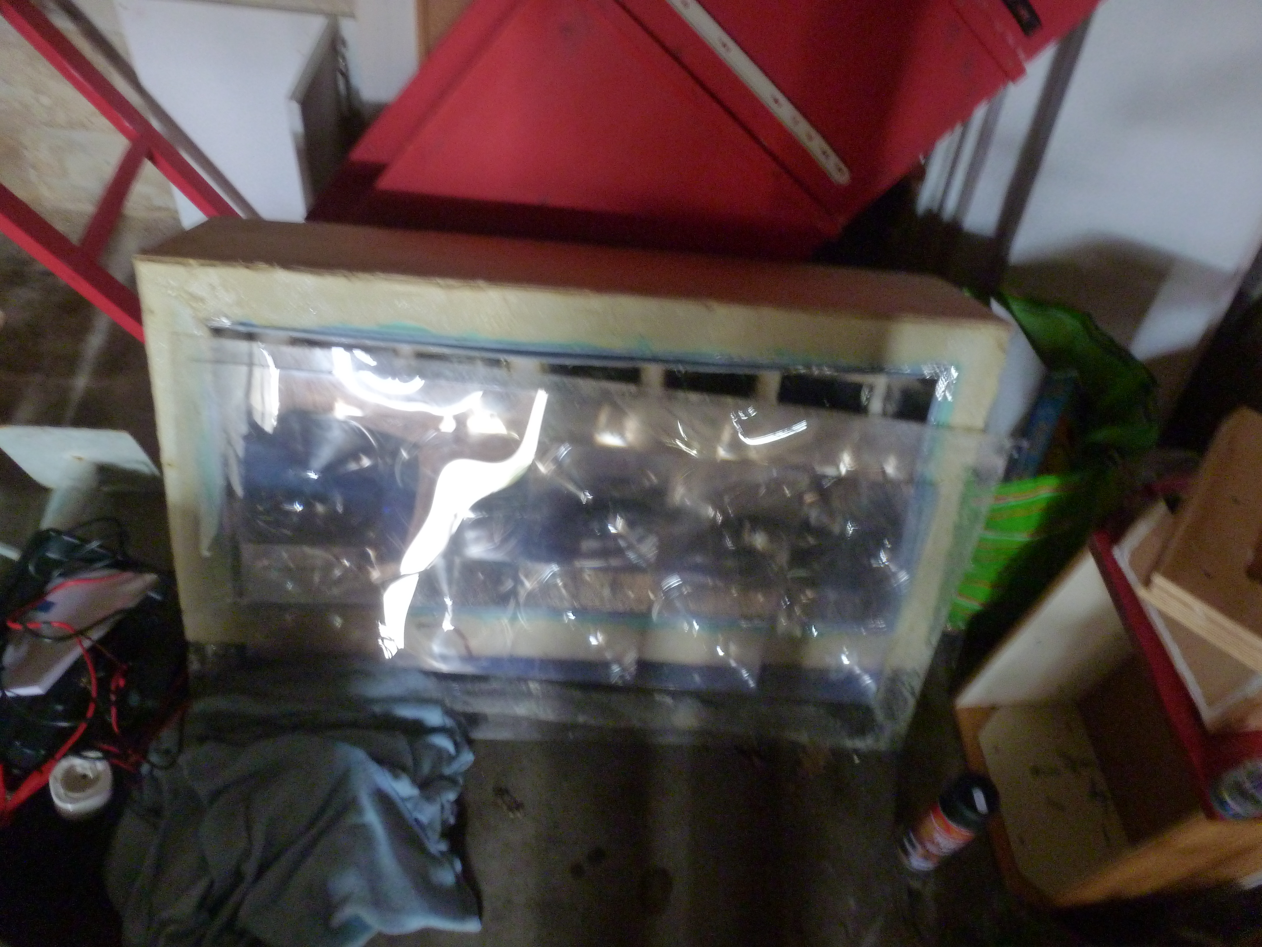
2) battery test 2
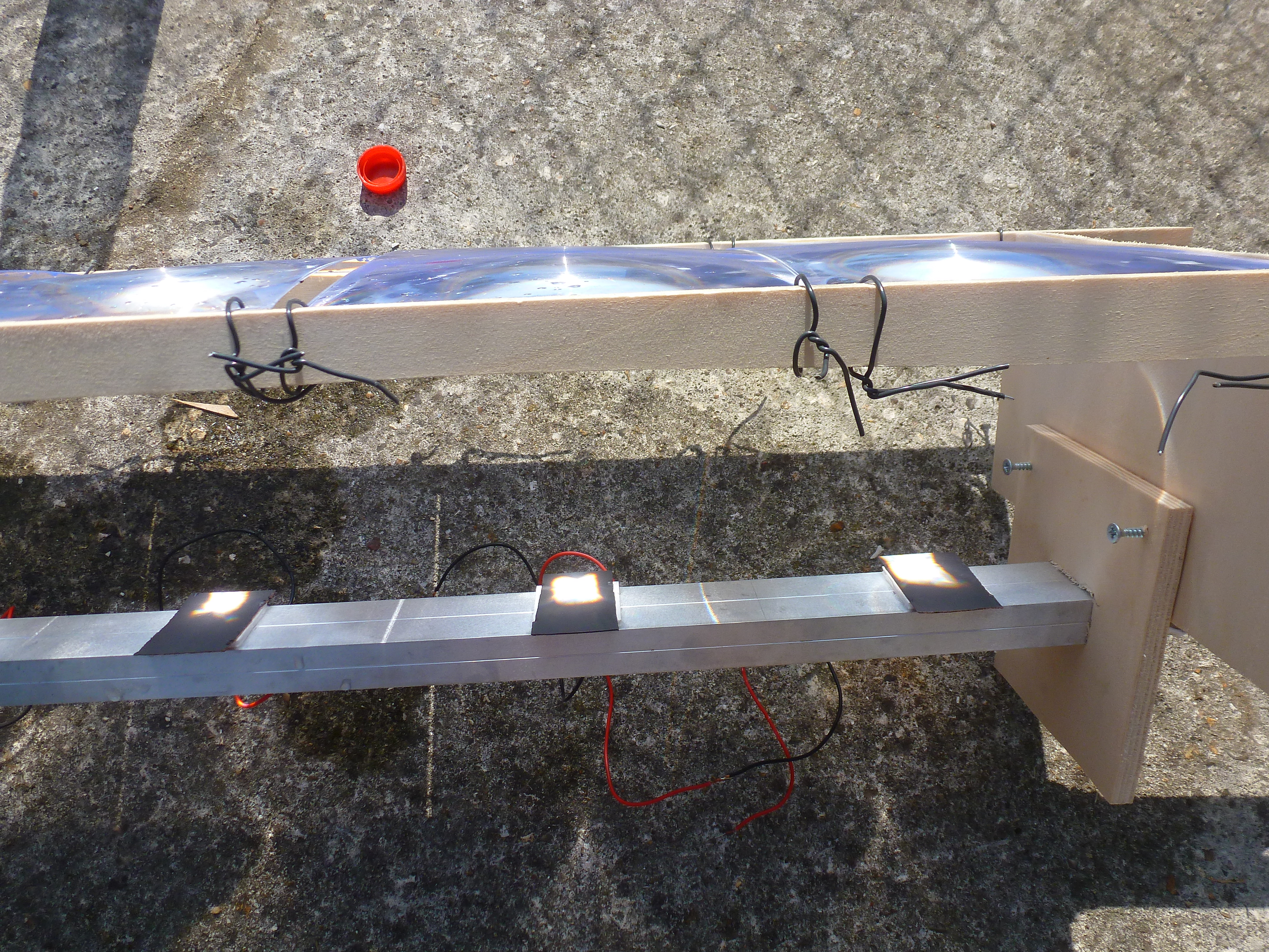
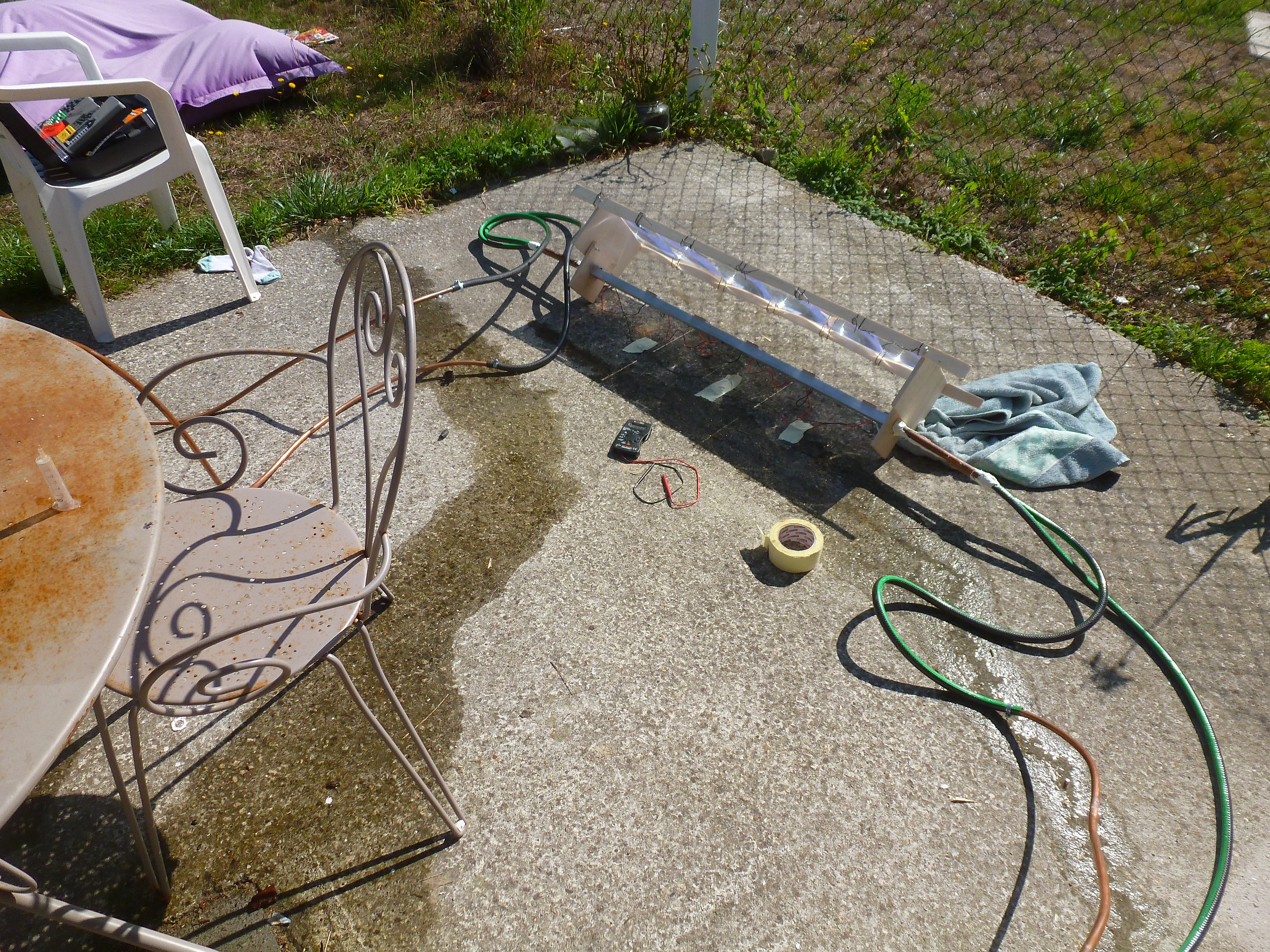
this time for this new model i have used 6 Fresnel lenses, 6 peltier's modules, a rectangular section of aluminium 1 meter long, 2 copper tubes with a diameter of 18 mm, a wooden board to make the lenses support, and a copper roller. for links i have used serflex and mastic. and of course i have used a hose too :
to make it it's really easy, on the aluminium section i have stuck peltier's modules (only on the corners to avoid a bad heat transfer), and on modules i have stuck copper parts painted in black, useful to grab the light focused with lenses (it's fireplace painting). Then in the aluminum section i have fixed 2 copper tubes, and i have shut 2 aluminium section's holes with mastic. then i have fixed the lenses support with an eye on a light focus not too concentrated (otherwise it makes the paint burning).
after this i have fixed 2 radiators with the copper's roller. each radiator is linked to a copper's tube.
it's working easily: the lense focuses sunrays on the copper part painted in black so it heats, heating also the module . the peltier's module is cooled thanks to the rectangular's aluminium section filled up with water and including copper tubes linked to radiators, also filled up with water. in fact the alu section is used like a heat exchanger between modules and radiators.
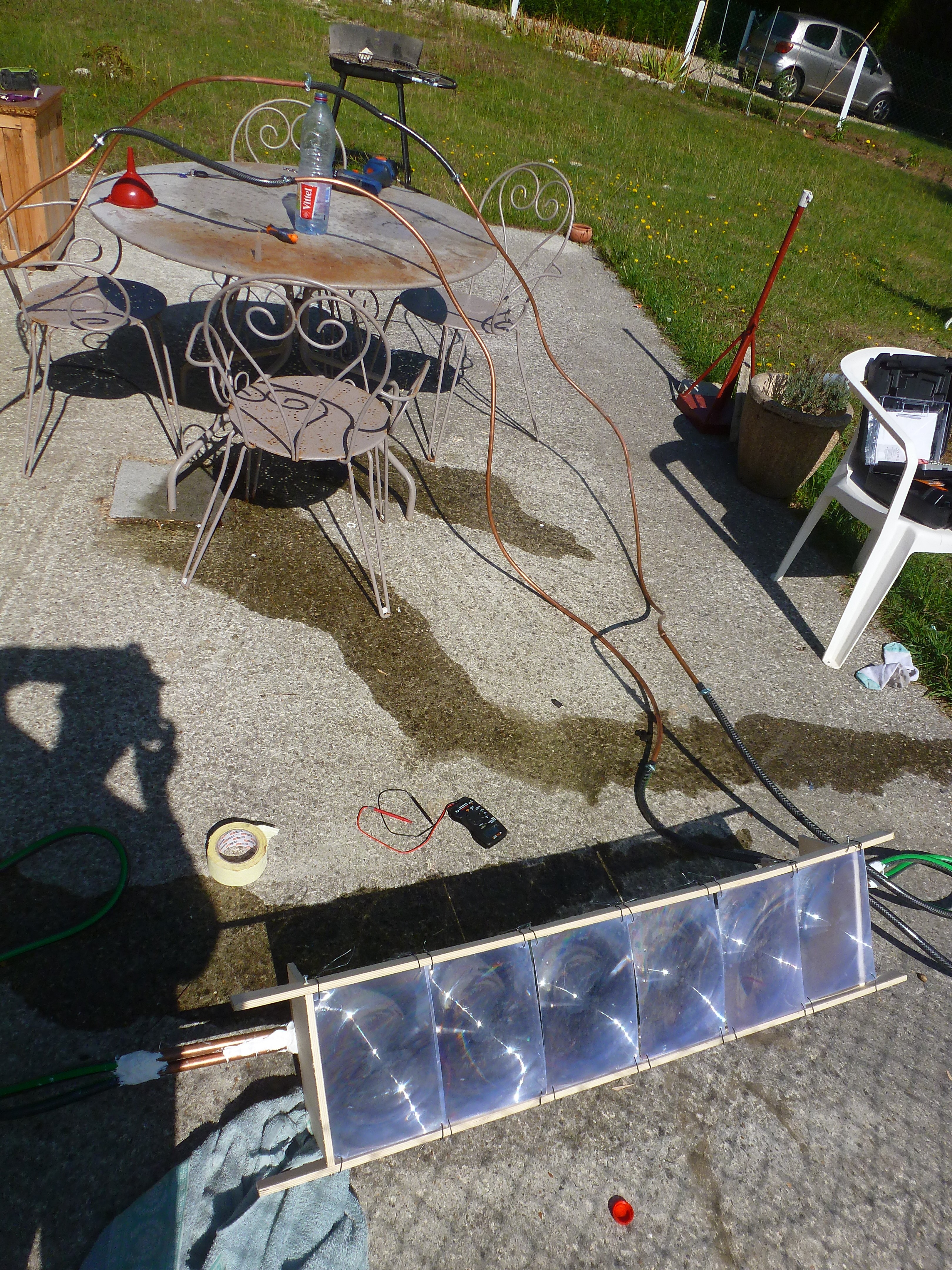
Résults:
This battery has been tested between 11h and 13h on 22 august. the circuit wasn't so watertight so i have added up 3 water bottles during 2 hours in radiators. i have used tap water at 17°C roughly.
11h10: 7.7 Volt / 200mA over
11h20: 7.8 Volt / 200mA over
11h30: 7.4 Volt / 200mA over
11h40 (first addition of water): 7.8 Volt / 200mA over
11h50: 7.9 Volt / 200mA over
12h00: 7.7 Volt / 200mA over
12h10: 7.4 volts / 250 mA
12h20 (second addition of water): 8.1 volts/300mA
12h30: 8 volts / 280 mA
12h40: 7.7 Volt / 270 mA
12h50: 7.7 volts / 260 mA
So this battery provides between 1.85 and 2.4 watts of power. during the test i had to move the pile a little every 10 minutes to have it in line with the sun. how far is it efficient ?
In the book “astronomical and mathematical essential for all ” (A. Moatti), the author tells us that the thermal sun flow grabbed on the floor is around 490 Watts per m2. This value varies with the position of the sun relative to our zenith, albédo, cloud cover… so we will just use this number to simplify. Lenses used have a size of 24.5/17 cm so in surface 416.5 cm2. i have used 6 lenses so it's 2499 cm2 then 0.25 m2. finally our generator can pick up from the sun 122.5 watts. So its efficiency is located approximately between 1.5 and 1.9 %. i should try an another test in winter this time to compare data, after improving the radiator's sealing. sure it's possible to win some efficiency again.
Part 3: thermal oil pile.
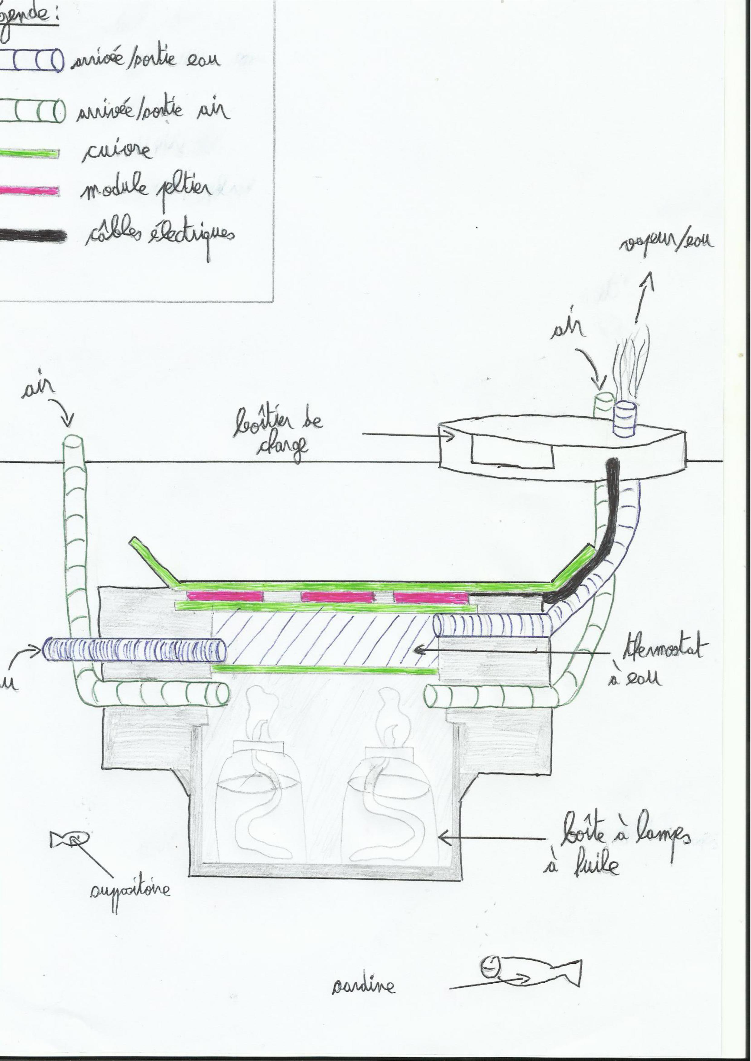
As we have seen at the beginning, the sea can perhaps do a great thermostat for thermal battery (So very useful to conduct heat), so currently i am making a diving generator working with oil burning (frying, colza, olive… in fact oil). oil lamps would heat copper, and copper in a second step would heat modules. The cool side would be just a copper board linked with the sea. Here's a diagram of the project:
For the moment i am just making the hot side but it brings several problems:
– for oil combustion we need oxygen, or if the hot part is immersed, it will be difficult to bring a sufficient oxygen volume .
– If the battery is submerged, then it must not have a big volume because of archimede (Archimede's principles) to keep it under water.
– if the pile isn't emmerged but is floating on the water, then we will have to isolate the hot side very well.
– We'll have to adjust the hot part: finding the good balance between heat/oil lamps distance to avoid modules burnt, or doing a thermostat (see the little draw) for limiting the heating temperature of the modules (in the case of the draw it's 100°C).
– heated well, copper changes its shape a little and it could damage modules fixed on it.
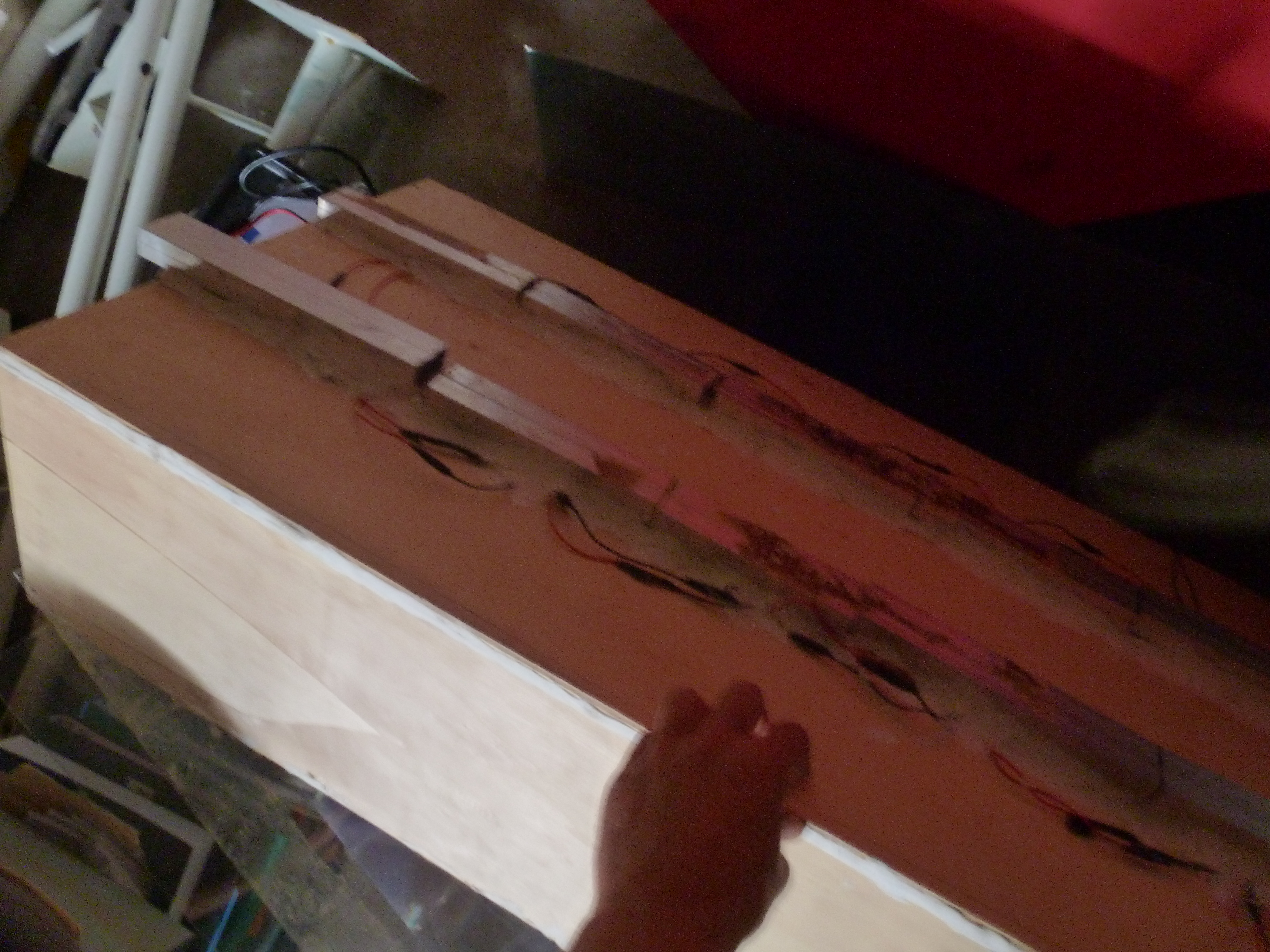
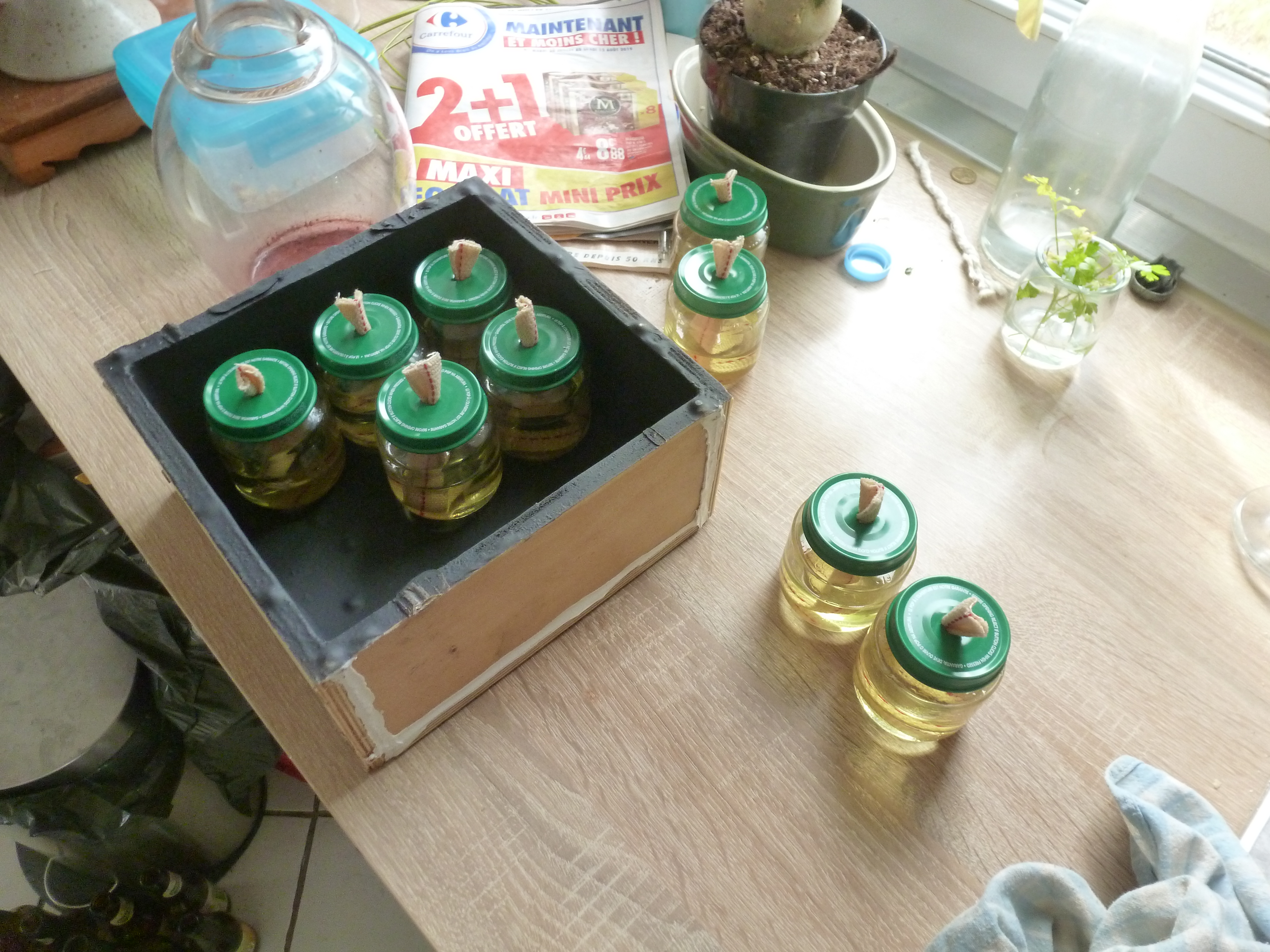
These are small pictures of were i am currently:
The box contains 9 Blédina cans (apple/mago taste, my favorites) acting as oil lamps. this box is storable in a copper and wooden cover with 8 holes 1 cm in diameter able to get space for oxygen. it's not efficient enough (only the central oil lamp is still working); if I just let this lamp after 5 minutes it heats the copper board until 50 ° C.
see you soon for the other part 4 I'll try not to take 2 years to do it this time !
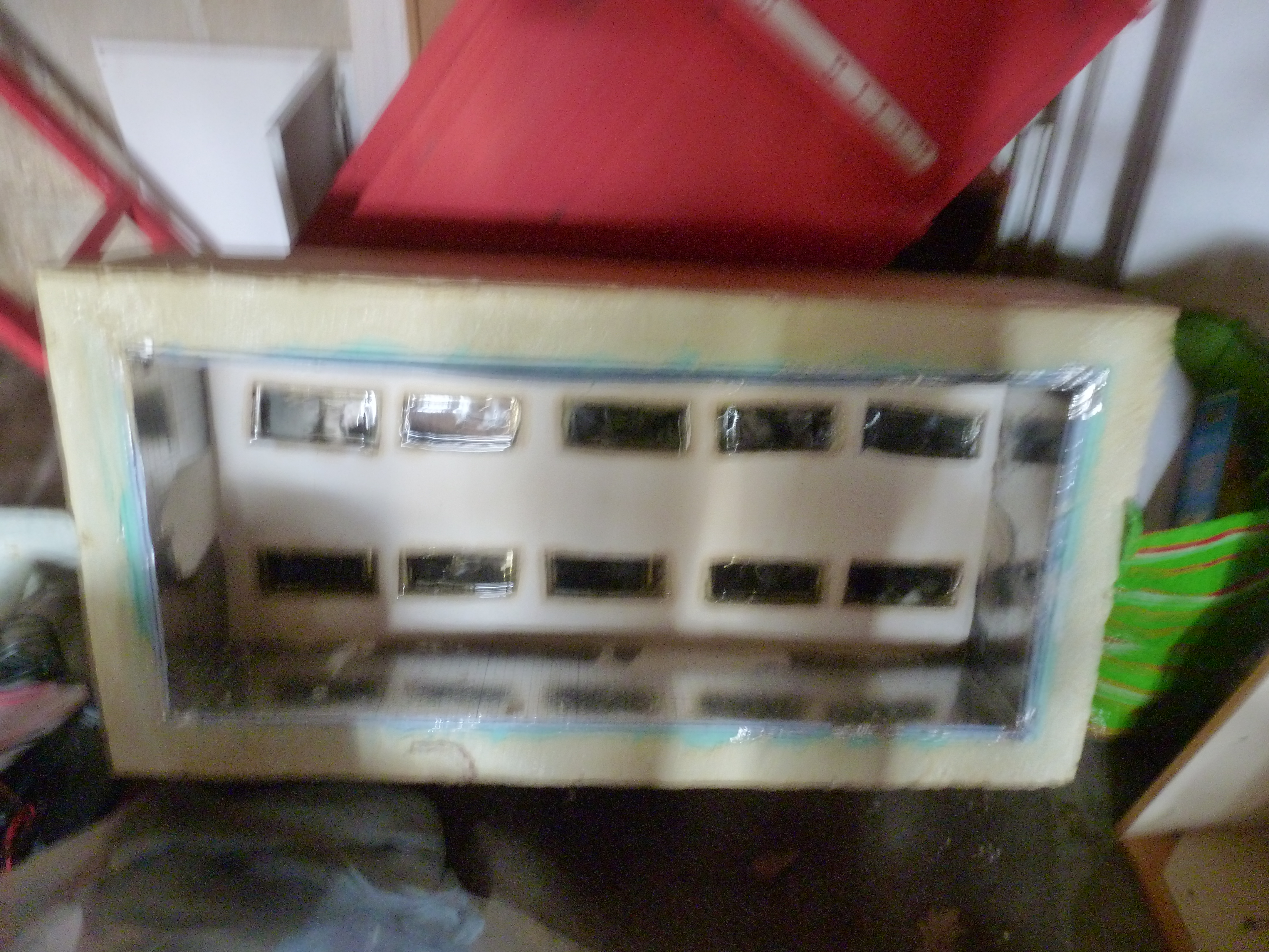
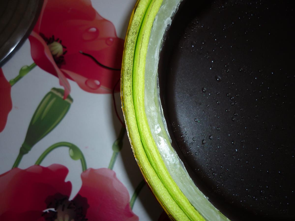
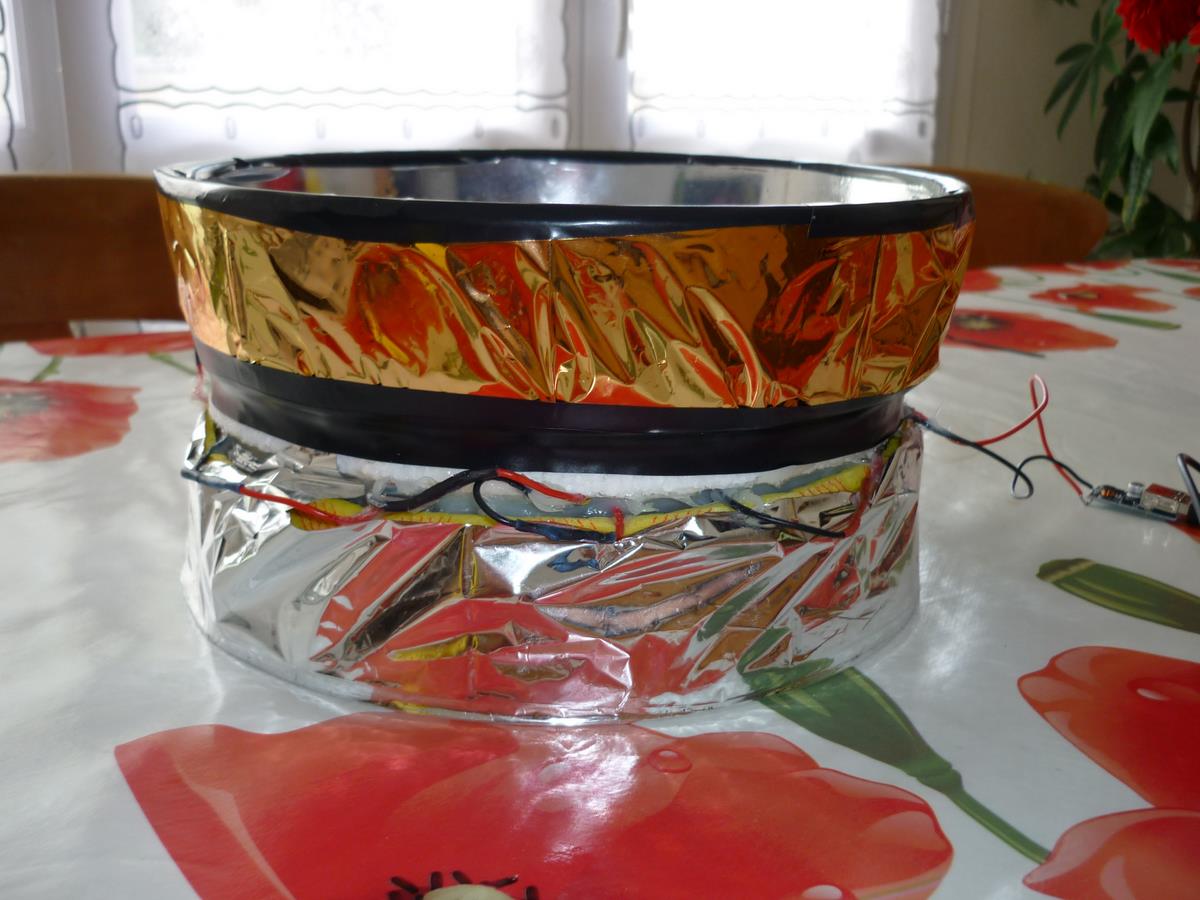
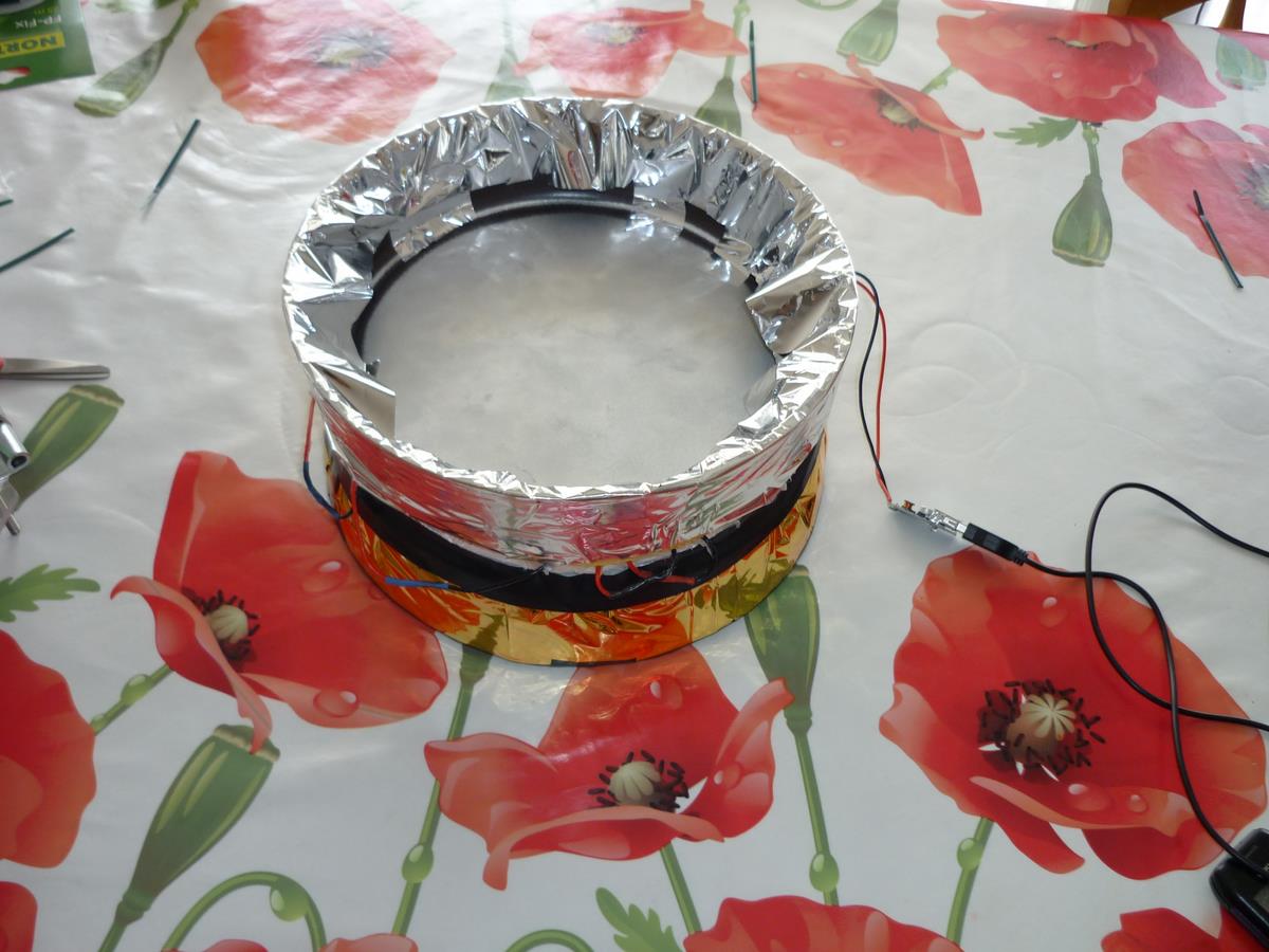
after the previous results, it was necessary to add or change a few things on the generator to try to make it more efficient; the cold side has been changed in a water tank (i have welded an another alu mold on the edges of the first mold “cold part”), sponge parts have been removed, and the hot side isolation has been improved with several layers and mastic. regarding our thing mirrors have been removed too and changed with a silver sun visor (more efficient and cheap, and easier to find in second hand), pvc window has been changed with double glazing to improve isolation.
on the picture we see molds, and silicon on the link to seal everything.
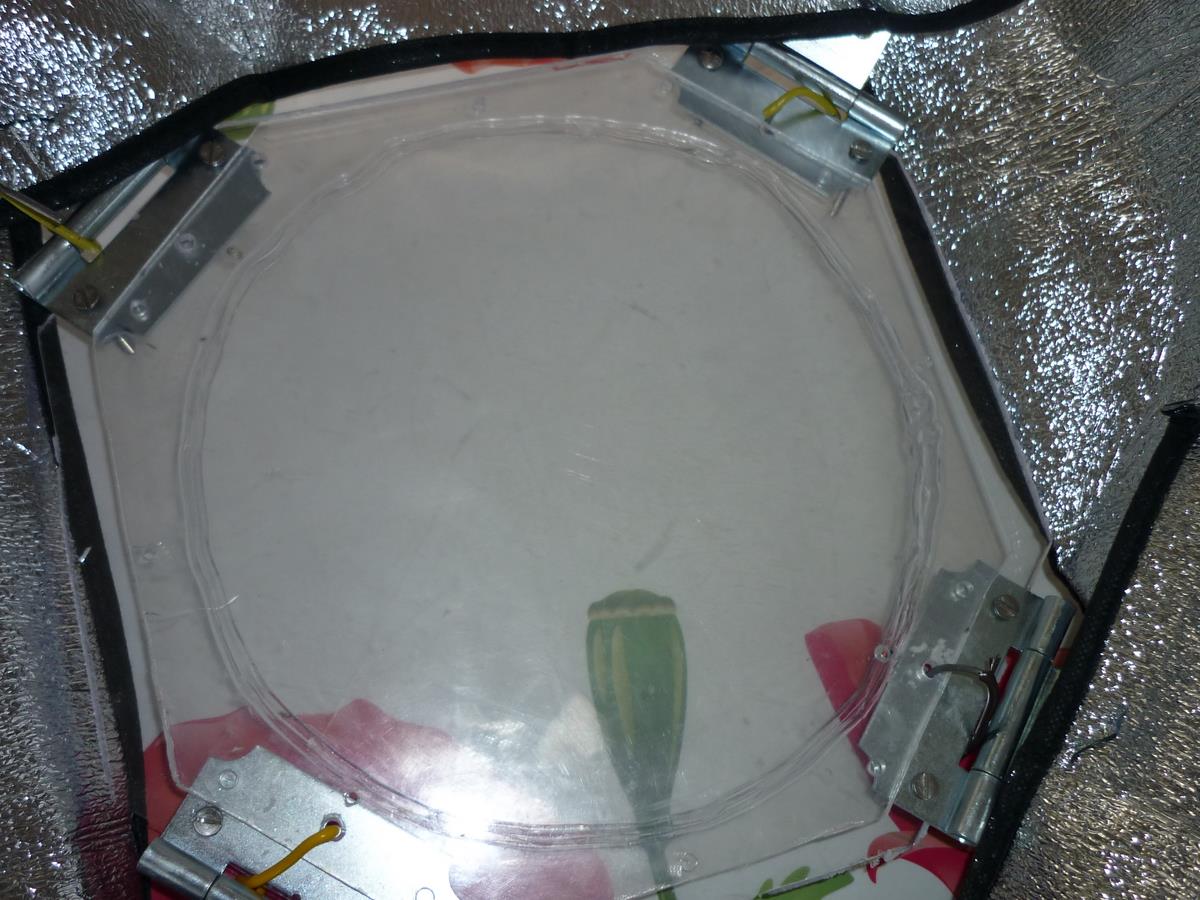
three isolating layers have been added up, stuck everytime with mastic. on the edge's mold “heat part” i have made a flat mastic seal on the top to improve isolation. when the window is put, it pushes first on the isolating moss and in a second time it touches the seal (to avoid hot losses).
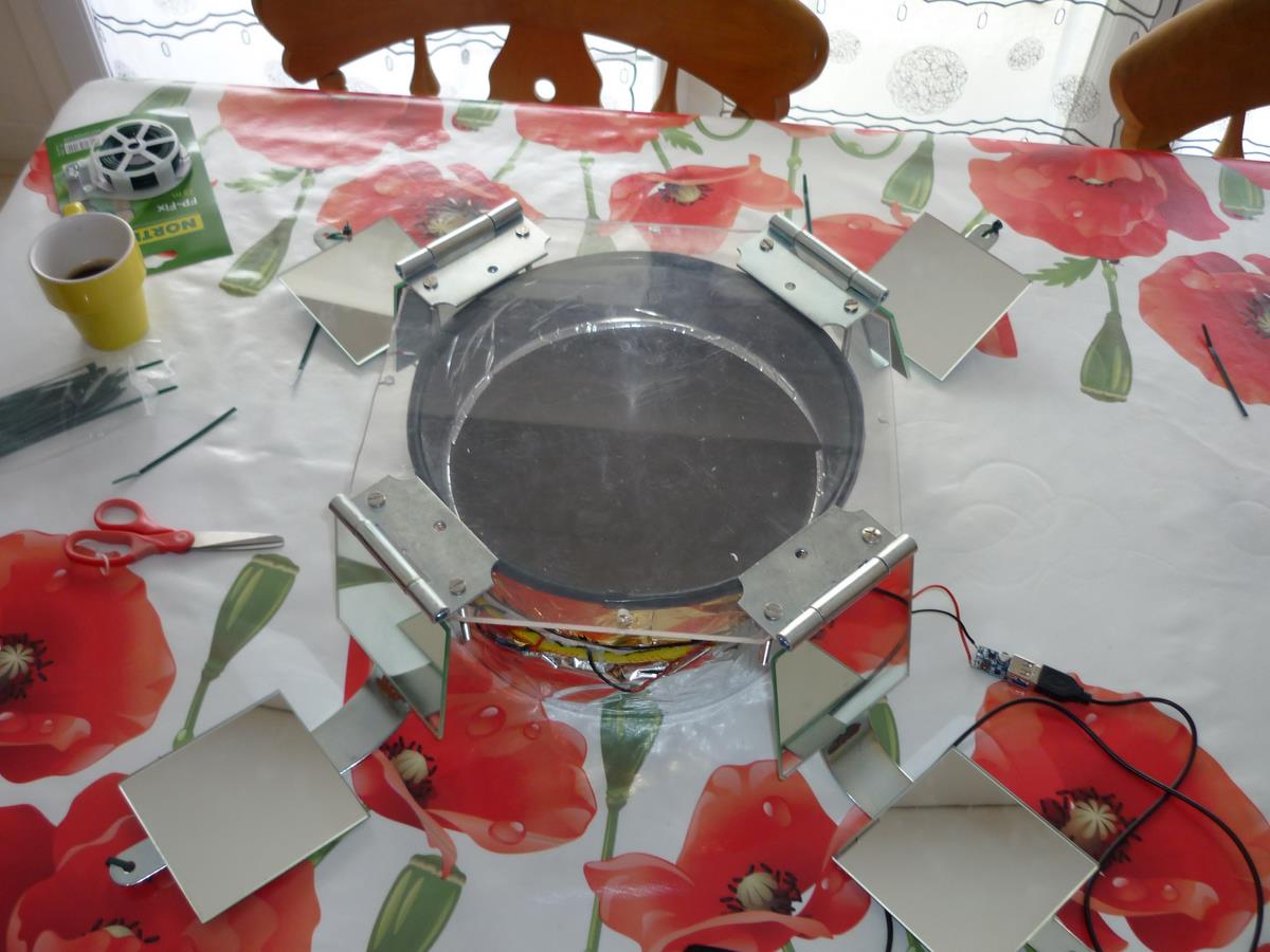
i have kept hinges and hangers, but this time to catch more light i have cut a sun visor 4 in four parts.
on the window used at the beginning i have stuck a second window, between them i have let a little space 5 mm roughly. by this way we get double glazing able to improve isolation.
1) solar energy
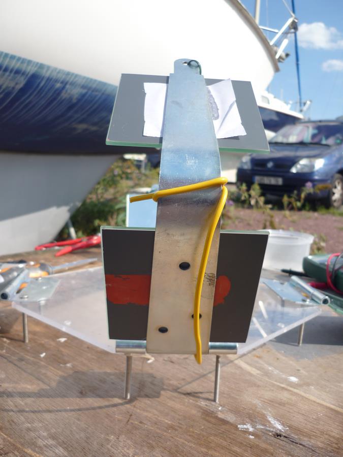
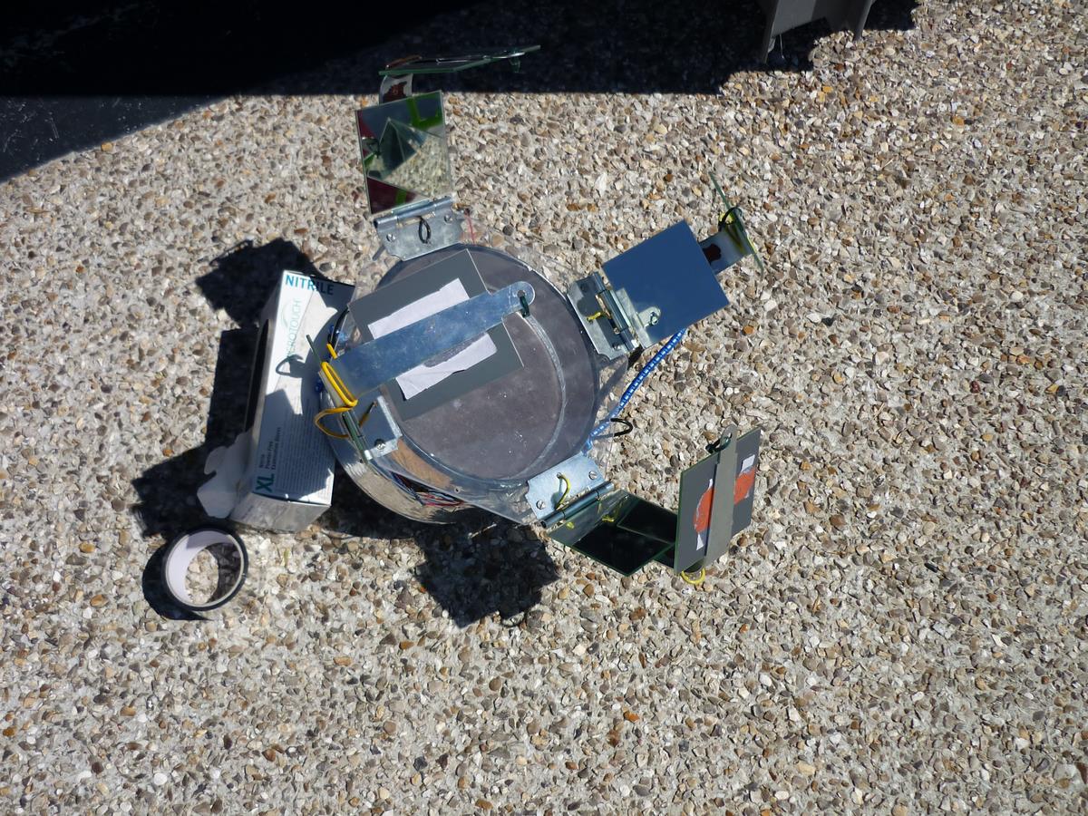
when our generator is used with sun, like a solar oven it must be set up in face with solar energy; or sun is never moveless in the sky so it must be moved steadily because we have to follow the sun. To have a good link between sun visor, window and our pile’ to avoid hot loss as well as possible, i have used sandows.
by an october normandy day well sunny, not overcast at all, and with water 15 degrees used like a cooling system we get that :
14h55: departure
/15h00: 2 V and 74 mA
/15h10: 2.45 V and 88 mA
/15h20: 2.7 V and 97 mA
/15h30: 2.62 V and 87 mA
/15h40: 2.71 V and 98 mA
/15h50: 2.92 V and 103 mA
/16h05: 2.73 V and 90 mA
/16h15: 2.75 V and 92 mA
/16h25: 2.56 V and 87 mA.
still in october, this time with some clouds:
16h20: 0.6 V and 20 mA
/16h25: 1.57 V and 58 mA(and sunrays)
/16h31: 2.55 V and 83 mA(then a fat cloud comes)
/16h40: 1.75 V and 63 mA (and sunrays again)
/16h50: 2.65 V and 95 mA
/17h00: 2.63 V and 95 mA
/17h10: 2.7V and 96mA (then overcast again)
/17h20: 0.8V et 23mA.
Conclusion: compared with our first try (done in summer, in august) we get roughly 1 V and more intensity. we could improve it; by increasing thermal isolation, and why not by improving water cooling system (which tends to heat up in time, thus lowering the voltage got since the beginning).
2) boiling water
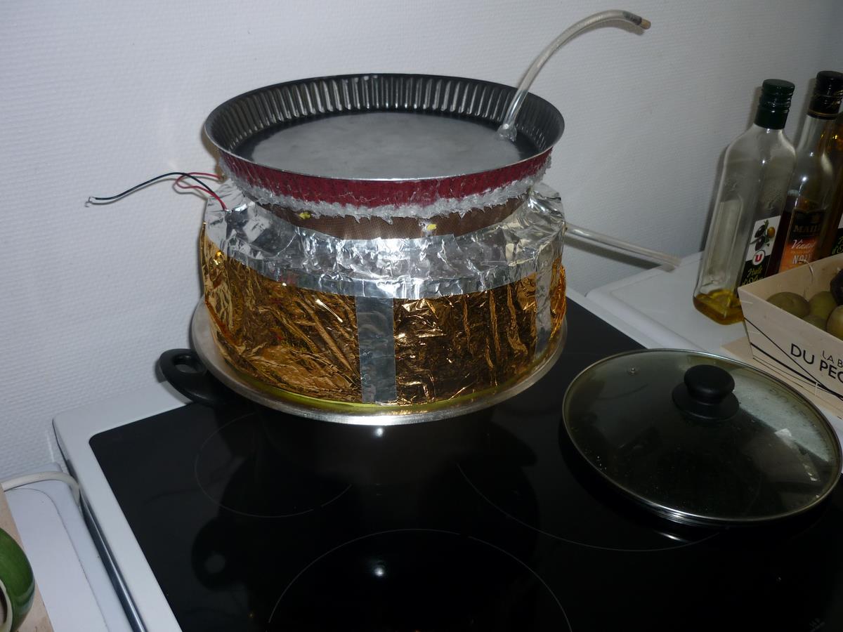
as we have seen at the beginning, we could not indefinitely heat peltier modules, if we exceed 100 degrés , we could damage it. if we heat them with water steam from boiling water we will be sure to stay under this limit 100 degrees , then to protect our system. we set up the heat side of our pile down on an aluminium lid perforated to let water steam run, then all on a water boiling recipient :
there is no contact between the pile and the aluminium lid thanks to mastic added up on our mold edge “heat part” and moss isolation. having filled up cold part with water at 15 degrees we get those following results:
16h13: the beginning
/16h15: 0.5 V and 23 mA
/16h20: 7.53 V and 2.3 A
/16h25: 7.41 V and 2.5 A
/16h30: 6.23V et 2A
/16h35: 5.19V and 1.8A /
16h40: 3.9V et 1.4A
/16h45: 3.4V and 1.1A.
At the end cooling water was at 29.5 degrees .
Conclusion of our story:
to get an efficient thermal pile, it is needfull to have a heat circulation as good as possible beetween heat and cold parts (i think that heat should be seen like a river that would have to keep a steady debit to move our mill's wheel, so our modules). So we will try to do 2 separate piles; one pile working with sun and an another working with fuel (wood or oil for exemple).
for the sun pile i will try to make a wooden isolated box heated by fresnel lenses and cooled with air or water, and the other we will see (probably heated with combustible then cooled with water).
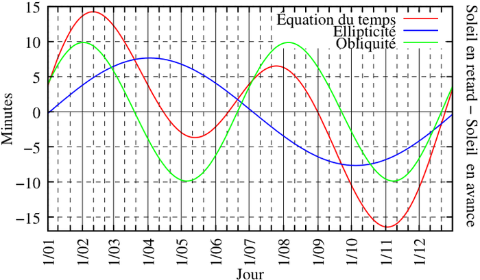
To make a program usefull for our position and working with the Sun., equation of time has been used, thus difference between solar average time and solar true time. This equation includes the true speed taken at "t" time of earth around the sun, irregular speed in time because of its elliptic way (see Kepler's laws). Now let's see how this equation was found, method found should maybe help us later in case of planet path calculations usefull for navigation too (Mercury, Venus, Mars, Jupiter, Saturn), knowing that to write a position program with planets we will have to change of referentiel (from a heliocentric to a geocentric referentiel, something about). To write this article i have used a lot "the theoretical minimum" written by L. Susskind (not always easy to understand quickly but really interesting, I used his book on classical mechanics) and also physics courses available on youtube of Richard Taillet (mechanical, semester 2, course 3), very clear and well explained where from motion equations he proves elliptic path and Kepler's laws for 2 systems. Well I hope I have not let too much bullshits in the summary of all these steps.
(With this diagram just above, we can see all along a year the shift between the average sun where the earth spin theoreticaly around drawing perfect circles, and the true sun's path)
1) classical mechanics stuff
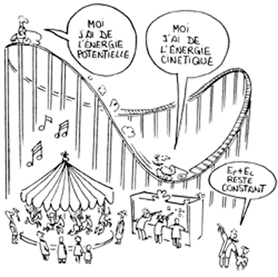
A system can be resumed in mechanic as a sum up of kinetic energies (Ec) and potential energies (Ep) assigned to it, it's all the system energy (And). kinetic energy could be seen as a kind of "motion energy" of the system, and potential energy, as noticed by its name, energy that could be released by the system (i hope this def is not so bad). For example if we put a ball at the top of a building, ready to be dropped, then at that time its potential energy will be at its peak, and its kinetic energy will be at its weakest level (because the ball is motionless relative to the referential building). Now if you grab this ball just before its crush on the floor, its kinetic energy will be at its maximum (the ball reaches its maximum speed) but this time its potential energy will be almost minimum (it will be at minimum when the ball will hit the ground).
therefore in physics total energy is written like this :
Et = Ec + Ep = 1/2 mv ^ 2 + V(x), with V(x)= Potential of the system. I rated it V(x) because the potential depends on the position of the object studied in a given referential (with our exemple of the ball on the building, the more our building will be high and the more our potential ball will be strong it's nearly that).
with all those things it's possible to find motion equations of an object. but before going a little further it's interesting to define other things (but not too much it could be bothering ).
a) The potential energy
For central force systems (like planets which undergo a star or an another planet gravity, which can be similar to a point) it's possible to define that the sum up of forces working on the object are equals to negative potential energy gradient : ΣF = -grad(V), there is a negative symbol before grad because the object is attracted towards the point (so acceleration written with a vector will aim at the point if we would draw a diagram of it). We can also define force as follows :
Fi(x)=-∂V(x)/∂xi ; This thing means that the force expressed on a spatial way of the system (here xi) is equal to potential partial derivative compared to this spatial way... I guess. We could also say that a force it's space divergence of a potential energy (in mikado backflip the most of time but well let's go a little further).
According to Newton's laws the sum of the forces is equal to the product of mass and the acceleration of the object. so ΣF = ma. That explains why when the acceleration of an object is zero (motionless object or with a constant speed), then the sum of the forces applied to it equals 0. A force is just an accelerated mass.
b) derivatives, integrals, partial derivatives
derivatives, partial derivatives
For potential energy we have seen gradient, but what is it ? It's just the sum of space partial derivatives of V potential ; so it's :
Grad (V(x))= ∂(Vx)/∂x+∂(Vy)/∂y+∂(Vz)/∂z
a derivative function in regards to time shows its time rate (we will then talk about velocity, it's the object speed compared to a way choosen in a choosen referential, Cartesian for exemple) but it can also be done in space if the derivative function is derivated regards to space. In fact we could easily derivate a function with any of its parameters (for functions with several variables), not always just time parameter.
The second derivative of a function indicates the rate of change of the first derivative. If the first derivative is velocity, then the second derivative will be object acceleration according to a way choosen in our landmark .
Usually derivatives allows you to notice how will evolve your function (increasing, decreasing, stationary…) and second derivatives are useful when you need to find maximums and minimums in a local range of a function, and other things like making coffe or learning how to understand women.
The derivatives are not exclusively reserved for functions with one variable, they can also be used for functions depending on several variables ; we will then talk about partial derivatives. The idea is almost the same except that when we derivate a function regards to one of its parameters, we consider the other parameters like numbers or simple coefficients. For example, considering the function F(x ;y)= 3x + 2y. If we do ∂F(x ;y)/∂x it gives = 3, and if we do ∂F(x ;y)/∂y = 2 is obtained.
integrals
It's a bit the opposite approach of a derivative, if we could say it like that. if we should define with accuracy this thing we could say that it's an amount of areas under a function. we could deduce that potential is equal to negative integral's force with constant : V = -∫Fdx+constant. nevertheless here we will give up constant (see the principle of gauge invariance for the curious). So it gives V = -∫Fdx.
c) Lagrangian
in physics, Lagrangian is usefull to find how a system will change with time and space, deduce motion equations, and identify potential symmetries, Its a bit like a swiss knife in fact...Usefull to find action's system too (see the principle of least action for the curious).
Lagrangian : it's just kinetic energy without potential energy of an object studied (at least for our planets, but this is not always the case for all systems), So it gives : L=1/2 mv^2-V(x). The Lagrangian can be considered as a function working with 2 variables, a space variable (induced by the potential energy) and a velocity variable (induced by the kinetic energy). It gives at the end L=L(xi ; dxi/dt). (Dx / dt = velocity on x axis and xi means axes, y and z).
symmetry : In physics it's when we have a lagrangian invariance when the system is moving in one freedom degree (Here we talk about space configuration with degrees of liberty in space, x, y and z). For example, angular moment is a rotation symmetry. so we get dL / dt = 0 in a Lagrangian symmetry linked with time.
d) Euler-Lagrange
This way allows us, with the Lagrangian's help, to find the combined moment of a system (it will help us to detect the system symmetries) and motion equations.
combinated moment : it's lagrangian's derivative regards to velocity.
Euler-Lagrange equations : it's just : (d/dt)( dL/dVx) – (dL/dx)=0 (for a single freedom's degree, here x. Vx is x's derivative with time, so it's velocity).
2) Find motion's equations of a system around the sun.
a) The Lagrangian in polar coordinates
We will first try to define the Lagrangian of the system in an orthonormal system (x, y, z), then we will change it to work in a polar way(r and ө, r = radius, in fact distance between 2 systems and ө = angle).
The kinetic energy : it's simple, It's Ec=1/2 m(dx/dt)^2+1/2 m(dy / dt)^2. It is considered that the object moves in a single plan (x, y) thus we get rid of z. If we would have taken care of z we would have spoken of cylindrical polar coordinates.
The potential energy : we will do a little magic trick ; we almost all know that the gravitational force between 2 bodies defined by Newton equals GMm/r^2 (proportional to the product of the masses and inversely proportional to the square of their distance between them). Or we have seen that V = -∫fdx ; so if we integrate GMm/r^2 we will finally get V(r)=-GMm/r (because the potential depends on the distance r which is a variable parameter, G, M and m are considered as constants, remember the example of the skyscraper and the ball).
We know that the Lagrangian is the difference between kinetic energy and potential energy, so :
L = Ec-Ep = 1/2 m(dx/dt)^2+1/2 m(dy / dt)^2+GMm/r
Now we will convert our Lagrangian in polar coordinates. It's more convenient when you want to study a rotating object around an another one. There will be 2 degrees of freedom : r which is the distance between the 2 stars and ө which is in degrees the angle between the pericentre and the position of the rotating object relative to the focal (the sun).
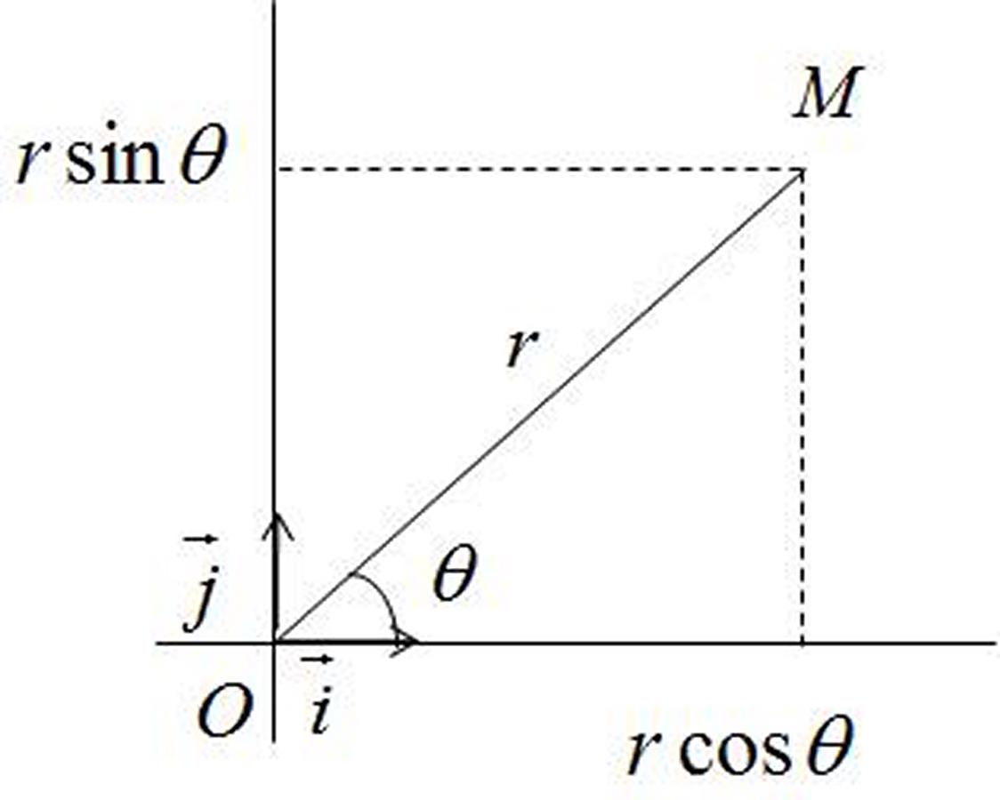
According to the small diagram so we can convert the Cartesian coordinates into polar coordinates as follows :
X=rcos(ө)
Y = rsin(ө)
Then we will just have to substitute in our Lagrangian those new things ; However, in the Lagrangian we talk about velocity but here we have positions only. Before touching our Lagrangian it must will be unavoidable to calculate the first derivatives of X and Y. Taking into account that they are functions products (r with cos(ө) and r with sin(ө)), and ө be regarded as a dependent function of time (so cos(ө) and sin(ө) should also be considered as composite functions in our calculation of derivatives), we will find that :
X’=r’cos(ө)-sin(ө)ө’r (the 'means time derivative, useful to write faster. For example r 'is the time derivative of r).
Y '= r'sin(ө)+ө'cos(ө)r
If we take our derivatives and we stock them in the Lagrangian instead of our first coordinates , we get :
L=1/2 m(r’^2+ө’^2r^2)+GMm/r, in fact our Lagrangian in polar coordinates.
b) Motion equations
This time we will grab in our toolbox Euler-Lagrange equations. We will use it for our 2 degrees of freedom and it will give us :
(d/dt)( dL/dr’)- (dL/dr)=0 and (d/dt)(dL / dө ')-(dL / dө)=0
When it's solved, we get 2 equations :
r''=rө’^2-GM/r^2 (r '' is the second time derivative of r, acceleration then).
(d/dt) (mө’r^2)=0 (this equation displays a symmetry 's system, thus a Lagrangian stability regards to angular velocity with time. In fact it shows kinetic moment stability of the system when it's spinning around the sun). We could also write this second equation in this form : mө'r ^ 2 = constant.
As we know that m is a mass considered constant, So then we could be more accurate and say r^2ө'= constant = C.
c) Getting a function of r kind(ө)
This function will allow us to determine the trajectory of a systaem by its polar coordinates. For that, we need the Lagrangian found just before :
L= 1/2 m (r’^2+ө’^2r^2) + GMm/r
We have also established that C=r^2ө’. This constant is simply the area constant, one of the three rules of Kepler's laws. Okay so now we will integrate this constant in Lagrangian's equation and it looks like this :
1/2 r’^2+(1/2) (C^2/r^2)= GM / r + constant (we note that if we simplify writting m disappered, so the mass of the moving object. So we can deduce that the mass of the object does not affect its movement around the main object).
Now we will try to transform our Lagrangian as a function r(ө).
It will then be necessary to determine r as a function depending on the parameter ө, knowing that ө depends on time t ; we will write mathematically :
r'=dr/dt=(dr/dө) (dө/dt) ; r 'is defined here as a composite function.
So in fact it also gives dr(ө(t))/dt=(dr/dө)( dө/dt), so at the end ө’(dr/dө).
From this writting we change writting of the function found before and we get :
One notices that the equation could be simplified, and it gives us :
(d^2 u/dө^2) + u=GM/C^2 , it will allow us to calculate u according ө therefore r according ө.
now we have to resolve a differential thing...Not won yet this story. If u is constant we have a solution GM/C^2, but it's still a special solution (it's just if the system's way draw a cercle in space, not an ellipse shape). The solution will be harmonic oscillator like this Acos(ө) + Bsin(ө), equal also Xcos(ө+ө0) with X the motion range. we find also the harmonic oscillator when we study pendulum motions or electricity for exemple. In fact we can deduce that :
u(ө) = GM/C^2 + Xcos(ө+ө0) ; and now it's nice , but we are seeking r(ө) in fact ! well yes then as r = 1 / u, then that's good :
u(ө)=GM/C^2 (1+ (AC^2/GM) cos (ө+ө0)) , – AC^2/GM it's the ellipse eccentricity which is written e.
So : r(ө)= (C^2/GM)/(1-e cos(ө+ө0)). The ө0 is pointless(it is useful if you want to shift function's period that's all) So we get our desired equation :
r(ө)=(C^2/GM)/(1- e cos(ө))
If e is equal to or greater than 0 but strictly under 1, then we have an ellipse trajectory; if e = 1 then our path will be parabolic, and finally if e>1 so we'll have a hyperbole. This equation allows us to guess trajectory regards to rotation's angle, but how to draw this trajectory with time ? In fact we will build the link first with a geometric method, and then by approximation using number sequences.
Small break about the harmonic oscillator : from the harmonic oscillator, solution of the differential equation seen before, we could express the trajectory's equation in an another way. Why ? because , this oscillator solves the following differential equation :
x’’+ Wo^2x=0 , as we can notice it looks like very similar compared to what we have found before : (d^2 u/dө^2) + u=GM/C^2.
In fact oscillator's equation describes a physical system following time without amortization, friction, on the neighborhood of a balanced and stabled position. Wo is a parameter called the natural frequency, it is equal to Wo=2π/To, To is the natural period of the phenomenon.
As we have seen the solution can be written x(t)=Acos(Wot) and y(t)= Bsin(Wot) (they are parametric coordinates), in fact A=xo (x position at time t = 0) and B=Vo/Wo (initial velocity divided by the pulsation). Why ? because when we put t = 0 then x(0)=A (because cos(0)=1 and sin(0)=0) and when we derivate y(t) and x(t) with time, we find y'(t)=WoBcos(Wot), and if we do y'(o) we get y'(o)=WoB so B=y'(o)/Wo (Y'(o)=Vo).
(seeking on google “harmonic oscillator without damping planets”, we drop on this pdf very well explained just above)
3) The elliptical path
P=C^2/(GM), this is called the ellipse parameter, so r=P/(1- e cos(ө)).
To calculate r max, the distance to aphelion just write ө = 0, we get r max=P/(1-e), and the distance to perihelion just write ө = 180 which gives us r min=P/(1+e). Then to get the diameter's half part of our ellipse we just have to use (r min + r max)/2 which is equal to a= P/(1-e)^2. So if ө = 90 °, that is to say if cos (ө)=0, then P=a (1- e)^2. To set geometrically all the parameters of the ellipse I introduced a small diagram to be clearer :
C = ae and b=a√(1-e^2). F is the focus of the Sun (the stationary sun serving as the origin), e the eccentricity and a the semi-major axis of the ellipse. C is the distance from the focus to the center o of the ellipse.
4) The equation of time
it allows us to get the real sun's velocity around the earth (when we use earth like our referential). According to Wikipedia it is made with center's equation and earth obliquity's equation. there is on wikipépé an another simplified version where we have built something around by using trigo functions, but we will rather stay focused on the first one, egg, ham, and cheese.
a) Center's equation
Here it is written in the form of a C function working with average anomaly M, thus C(M). The average anomaly is easy to define, it is the average angular velocity of a system or a planet which is mooving (we could also consider that it could be the system's speed if its trajectory was perfectly circular., in fact it's the way reached by the system in one rotation divided by time employed to run this rotation, that's all). So M is to be considered also as a dependent function of time t this time (So we can consider the function C as a composed function because C works with M and M works with t, in fact C depends on t).
There is Kepler's equation which is able to link average anomaly and excentric anomaly : E-e sin(E)=M, with M average anomaly and E excentric anomaly. However this equation doesn't include true anomaly v. The true anomaly depends on time, but on the diagram there is no geometric bridge between average anomaly and the others. However the previous equation links it to excentric anomaly, but problem : if we know average anomaly (thus time ...) we can not solve the Kepler's equation analytically, So we'll have to approximate a result, find an approximate solution to determine a position of the star regards to time (well ...).
to do this approximate work we will use series, and according to the eccentricity of the path we will employ :
. For an eccentricity's trajectory with e>e0 = 0.6627 ... Thus we will use a Fourier's serie (here, this is the case for objects with high eccentricities like comets).
. For an eccentricity's trajectory with e<e0 = 0.6627 ... Thus we will use a whole serie (For planets useful to navigate it will be whole series, like Earth).
b) Earth obliquity's equation
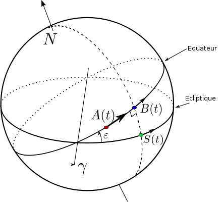
This is a function that depends on the ecliptic longitude LE so we can write it R(LE). It allows transferring the ecliptic coordinates into equatorial coordinates of the Sun, more helpful to use. Calculate LE is easy, it is simply the average angular velocity of the Sun around the Earth (geocentric reference) plus C(M) all this is able to correct this speed with trajectory's shape. R(LE) use a formula to make a link between ecliptic and equatorial coordinates (see diagram below).
In the diagram just above, Υ represents the vernal point (crossing the equator and the ecliptic to the ascending knot) ; ε is the slope angle between equator and ecliptic which is changing slowly during a long period. A(t) is any point dependent on time t, and motionless on an earth surface so it browses steadily in one sideral day . Point S(t) is aligned between the center of the Earth and the Sun., and makes one revolution per sidereal year, so it has an irregular rate over one year (because of its elliptical trajectory). And B(t) is the intercept between the S meridian(t) and the equator. We get then on earth surface a rectangular and spherical triangle in B(t), giving cos(ϵ)=ϒB(t)/ϒS(t), so YB(t)= Cos(ϵ) ϒS(t). So far so good after it gets complicated somewhat. Then to sum up all this, A(t) spins steadily, S(t) not so B(t) too, then in fact A(t) is connected to the average anomaly and B(t) is connected to the true anomaly ... It can be deduced that the angle between A(t) and B(t) is the true solar hour. Then Hv(t)=angle BA= angle Bϒ+angleϒA.
To define the average solar hour, we'll take the point A(t) because it moves steadily, and we will take an imaginary point derived from S(t) we will call it Sv(t) ; but this one we will imagine that it moves regularly. It gives : Hm(t)=angleSvϒ+angleϒA. As the equation of time is the difference between the average solar hour and the true solar hour, then E(t)=Hm(t)-Hv(t)=angleBϒ-angleSvϒ.
But we know that YB(t)= Cos(ϵ) ϒS(t), or ϒB(t)=tan(YB) and ΥS(t)=tan(ϒS), so :
Tan(angleΥSv + E)= Cos(ϵ) tan(angleΥS)
E(t)=-angleϒSv+arctan(cos(ϵ)tan(angleΥS))
Using a serie and putting y = tan(ϵ/2) for ϵ/2≈0,20, it gives :
R= arctan (cos (ϵ) tan(ϒs))-ϒs
R= arctan (cos(ϵ) tan (λs-π))-(λs-π)
R= -arctan ((sin(2λs) y ^ 2)/(1+y ^ 2cos(2λs)))
R = -y ^ 2 sin (2λs) + ½ y^ 4sin(4λs)-1/3 y ^ 6 sin (6λs)+….
Well, with all that we can do a little positioning program with the Sun., and perhaps also with planets useful for sailing, with the difficulty of referential change to add. For the moon it's more complicated because it undergoes a lot of forces and follows more intricated motions (three pieces problem), larger in a shorter time.
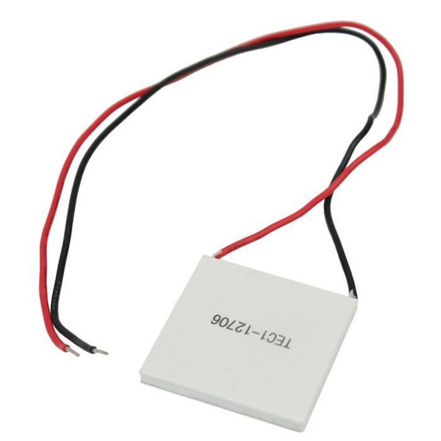
A couscous-maker designed by the Daft punk ? a space craft model from an ed wood movie ? after a first look it seems like nothing, but this thing is able to generate some electricity… by using thermal differences, in fact the seebeck effect (to do it well).
when we are hanging around on youtube we find videos called “incroyables expériences”, which are very interesting; we learn about how to build a Tesla coil, a loader, batteries, how does induction work… and when we are digging we find the video “thermopile”. on it everything is explained, seebeck effect, Peltier, a peltier piece framework, video is before all a seebeck effect demo, but the thermal generator showed and employed is not resistant against an another use (the oil light burns too fast peltier's piece). this little article try to show a "do it yourself" way to use this effect but several times.
1) Peltier's effect, Seebeck's effect
Peltier's effect (or thermoelectrical effect)is a physical phenomenon able to create a heat motion with the help of an electric current; to do that we lead the current on beyond two different materials able to conduct electricity and linked each other with junctions, step by step a junction will cool down and the other will warm up. we employ that thing for refrigeration. Some metal couples will be more efficient than others, A little like oxydo reduction reactions, we are talking about thermal couples.
seebeck effect is a little the contrary, and it will be our interest's subject.
2) peltier module
normaly the main fonction of this component is to create a thermal difference by using a DC current, the kind of module used here (12706) works on 12 volts. we use it for several things, including microprocessor's cooling system, little fridges's cooling systems for cars…and also draught beer systems. it has 2 sides, a cold face and a warm face, the object to cool down is fixed on the cold face and we set up an evacuation system for the heat on the other side(like the video seen on youtube “incroyables expériences”) like a little fan for exemple.
Nevertheless even if it's not conceived for that if we apply a warm source on the warm side and a cold one and the cold side, it will make a potential difference between its 2 terminals, so an electrical current. yield will be still weak . if we lay a module on a table with a voltmeter linked on it, and if we put our hand on the other face we will notice a slightly electrical current which will dicrease (the difference between thermal's module faces will be balanced quickly). we can have some fun by changing cold or warm sources: a hair-dryer, a magnifiying glass, ice cubes…obviously we get better results by using a cold and a warm source in the same time, if it's not the case after a little time temperatures between the module sides will be balanced, tension made will fall.
3) components and price
this generator made will have to follow some rules : don't be too expensive (because i'm greedy...and with a lack of money too) and able to work with one or two energy's sources easy to use, and employ a warm source no more than 100°C to preserve our peltier's modules.
to do it we will need several things :
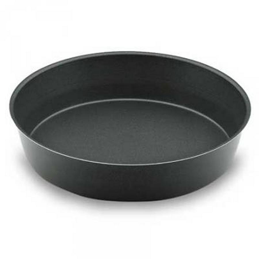
2 cake tins
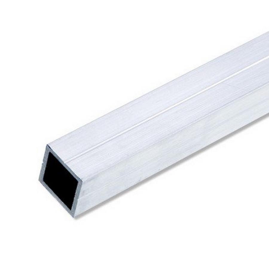
an hollowed squared tube in aluminium
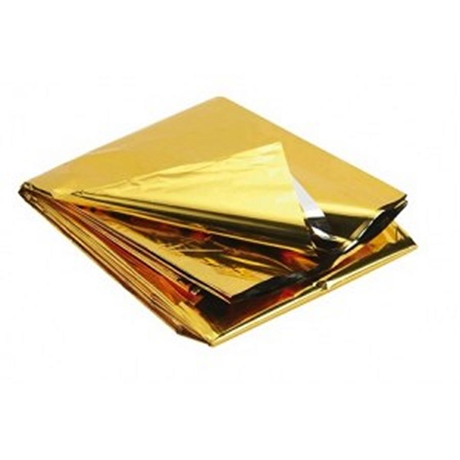
a survival blanket
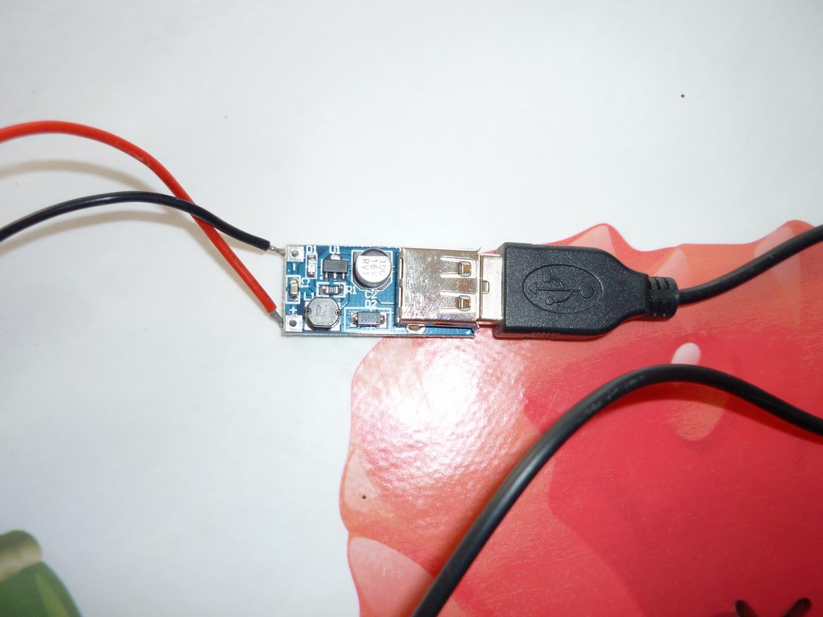
a booster able to increase the entry voltage until 5 volts at the exit and with a balanced voltage( CE8301 model).
we will need a polystyrene board too (as wide as the squared tube side in aluminium), silicon, a transparent pvc board (and strong against UV) , little mirors and a system to fix it (dorr hinges in my case). one will need 10 peltier modules too, and if it's possible some thermal paste. One will add up spongious towels .
finally, if we grab things people got rid of it, for about 25 euros we can do that. on the web ten peltier modules cost around the price of 20 euros, a booster less than 3 euros. after that if one is lucky it's maybe possible to get peltier modules in dead computers , some old iceboxes or in some draught beer systems (don't forget to make the barman drinking and let him drunk before), and little iceboxes in cars.
4) or DIY thing
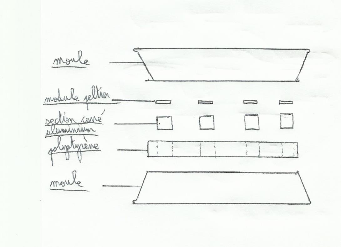
One begin to sand paint on cake tin's bottoms until the aluminium, on one of them one sand the depth of the cake tin too; this last one will be “cold part” of our thermal generator, so the first cake tin with only its bottom sanded will be “heat part”(it's better to keep the cake tins depth black for our hot part because it will be more efficient to grab and keep on it sun's rays, in fact heat).
one cut the alu tube . a peltier module has a squared shape with 4 cm sides. on my lucky day i have found a tube with a squared section with 2 cm sides, so i had to cut twenty parts (two for each module), a part has a length of 4 cm. tube i have found was anodized, so i sanded it to get rid of the anodyzed layer to have a better heat conduction.
one cut polystyrene board in circle with a diameter equal to cake tin bottoms, and in that circle one will cut ten squares with 4 cm sides. it will welcome 2 alu parts each. this polystyrene layer will be the isolation material between each cake tins.
one will then glue with silicon (with cyanocrylate glue it will dissolve polystyrene) the polystyrene circle on the cake tin “heat face” and dispatch alu parts in holes without sticking it on the cake tin.
Then one can fix peltier modules on alu parts, and link them in series connections:
before fixing it on aluminium, one put some thermal paste on alu (not too much, 2 or 3 narrow lines will be enough) and some strong glue in a weak quantity at each corner of each module. before sticking everything beware of module sides with “heat part and cold part”, a good idea is to check them with a voltmeter before fixing to avoid mistakes.
before sticking cake tin “cold part” one add up thermal paste on our free module sides , and then one stick cake tin with silicon.
At the end one adds up some silicon on junctions to isolate all the system.
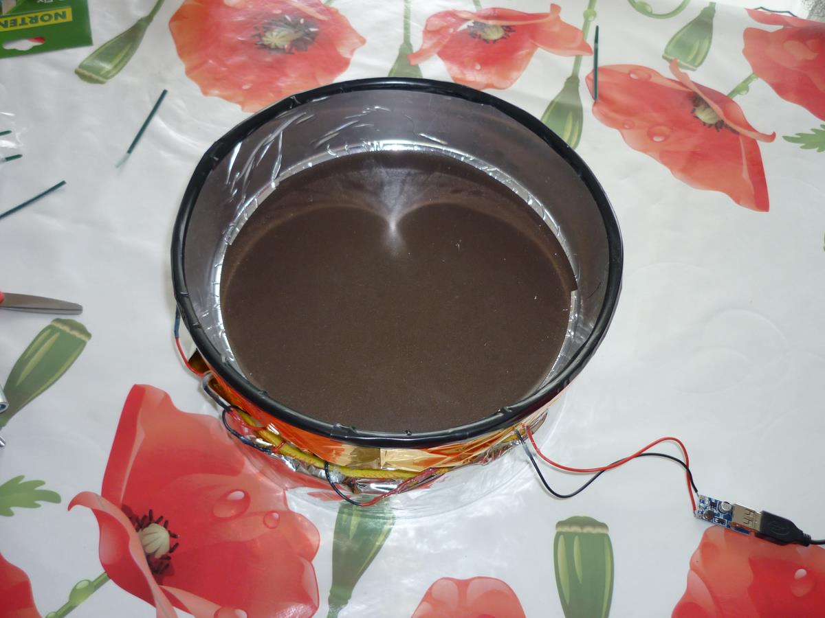
now the main things are fixed, one will isolate cake tins; on cake tin surroundings “heat” one will stick if it's possible a hydrophobic isolation material, for me i have cut a gym carpet (it also gives a good reason to give up gym) then one sticks on it a piece of survival blanket, gold side outside. around the cake tin “cold” one sticks spongious material. above one will set up a piece of survival blanket but this time with silver side outside.
5) How it works
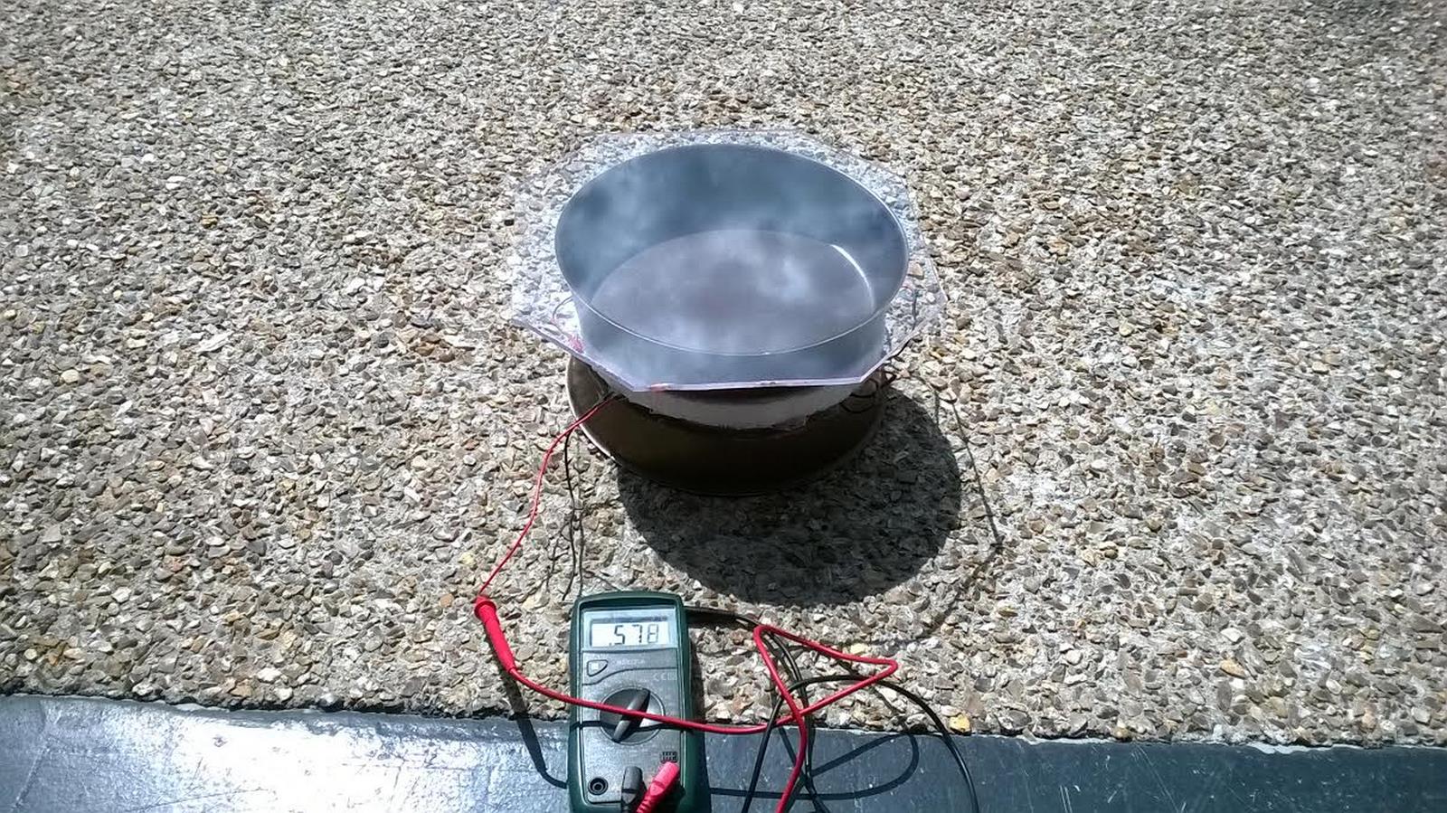
a. with the sun:
without thermal isolation, the system as it's showed on the photo, with an almost clear blue sky increases at the maximum of 1,1 volts for 20 mA after 15 minutes, and then falls and gets balanced at 0.8 volts roughly. we use the same idea than what is happening under a veranda or in a shut car (greenhouse effect). the black tin's color picks up heat easier, and transparent pvc “traps” infrared's wavelengthes, keeping more heat inside the cake tin. to improve tension's results one will have to isolate tins and try to grab more light aimed inside.
tin “heat part”
tin “cold part”:
on the last photo, we add up mirors fixed on little door hinges 90 degrees . to let hinges in the same position, one can use iron wire or a hanger easy to twist:
at the end we got this:
then when all that is done, we got those results (a shiny august weather in normandy):
+10 min=1.12 V; +20 min=1.6 V; +20 min=1.8 V; +30 min= 1.7 V (then balanced at 1.6 V). 45 minutes after if we spray on cold part some tepid water tension grows at 2.6 V. if we spray more it can grow until 3.7 V. 15 minutes after tension has come back at 1.6 V for 50 mA roughly. A 3.7 V we have 80 mA. when one spray tension increases quickly, falls and get balanced a little at 2 V (70 mA) but finally falls at 1.6 V. when we soak spongious material with water nothing happens, one should rather spray cold part on tin's bottom “cold part”.
b) with heat steam
One set up the system on its heat part, above a saucepan full of boiling water. beware of any direct contact between the tin and the saucepan “heat part” (to avoid too heat given to peltier's modules by thermal conduction), one can use cardboard pieces for exemple. water steam will heat heat part. we get:
the beginning: grows quickly and stabilizes at 2.8 V; +5min=2.65 V and 90mA; +10min=2.55V and 85mA; +15min=2.47 V and 83mA; +20min=2.3 V and 75mA.
then if we add up cold water inside the tin's cold part, we have:
the beginning: 7.5 V for 2.5 A; +5min=8V and 2.5 A; +10min=7.5 V and 2.5V; +15min=6.85V and 2.2A; +20min=6.55V and 2.2A.(the power provided decrease because water which is added up heat step by step).
now, we will see if we could use energy got to load a cellphone or AA batteries, for that we will link on battery 's exit the booster (DC-DC 0.9V-5V). with maker's data, by using an entry's tension between 0.9V and 5V, it provides a balanced 5V tension. on the booster there is a red del which adverts if it's loading or not.
from about 1.12 V my phone starts loading, However, after checking on the long term charge isn't working very well; although on the screen it's written in charge it seems to discharge battery. Charge on my cellphone seems to be correct when tension at entry's booster is at least 2.6 V and 80 mA (my cellphone battery is 3.7 V and 800 ma per hour).
on the market i have found an AA batteries loader with an usb plug. we could also change piles with an usb plug 12 V, and the can & rsquo; use it to charge a laptop with. By plugging loader on booster's exit nothing happens (the red dell is not shining), with sunlight and heat steam too (on the loader it's written that to work well it must have a tension of 5 V and an intensity of 0.5 A).
to improve our system we will have to improve thermal isolation, and find a better way to use sunlight, a little like solar ovens. with the solar energy used our main difficulty will be to work with a weak tension's exit to get it usable (each component brings an energy loss by Joule effect…), even if we use it just to charge only one AA battery (1.2V 2100 ma per hour). for heat steam's source we will have to find a solution to balance tension at 5 V, and maybe decrease intensity provided too to protect the loader or batteries. we will improve our cold part too by changing it into a water tank. Maybe it would be possible to use other heat sources…(chemical reactions..., maybe)
Quite easy to use(you press a button and pouf you have your position), the gps device is more difficult to understand, the main thing is that it will use the time as a measure for determining distances(between us and the appropriate satellites)and by intersection of these distances(like a point 3 of 3 bearings)it will display our latitude and longitude. Currently the number of satellites used for this system exceeds 24, and they orbit the earth at approximately 11000 miles. There is much to be sure that at least three are visible at any point on the earth at the same time. We will also see that the gps involves the laws of relativity of Einstein to obtain the best accuracy, no no this is not bullshit!
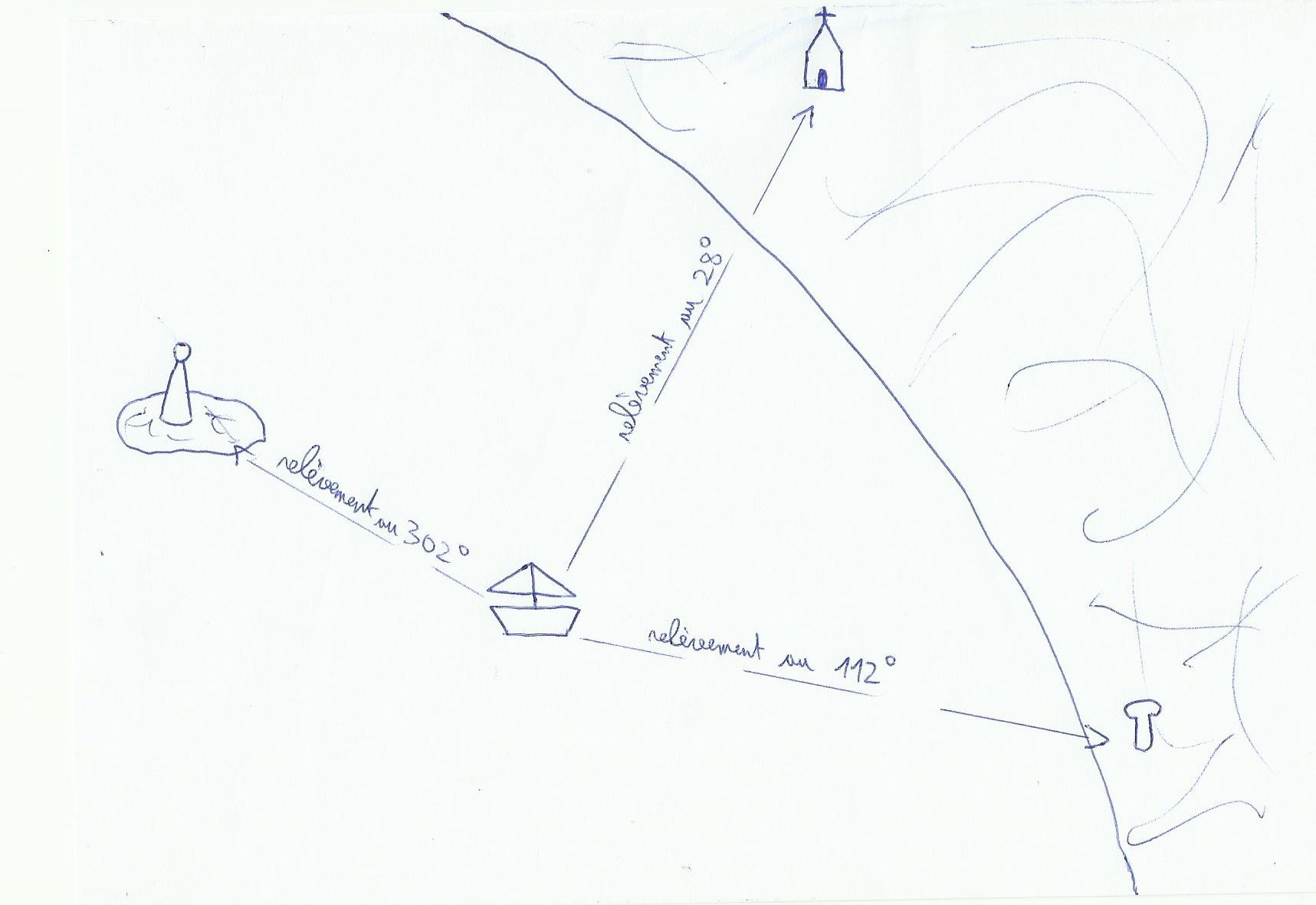
1) A three bearings point in 3 dimensions
In coastal navigation when we do a three bearings point and we draw it on the chart, we work on a 2 dimensions plan.
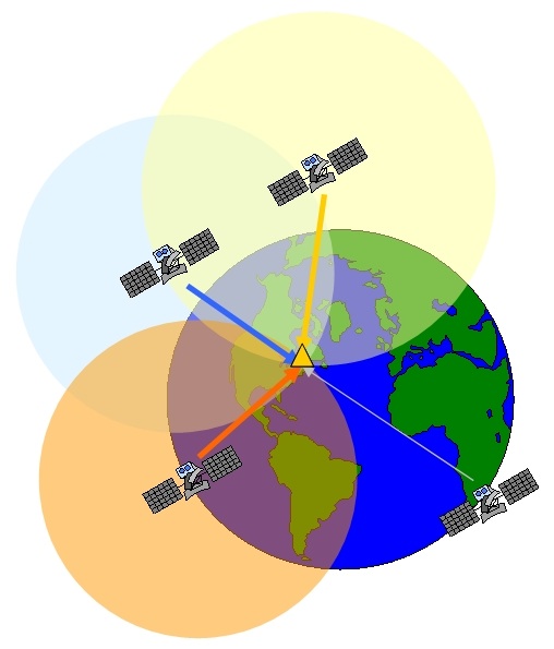
For positioning with gps it is the same idea except that here we work in 3D. A satellite's bearing will not store us on a straight line but on a sphere with the satellite as it center. The intersection of these three spheres indicates two positions, one on earth and one outside which will not be kept. The compass bearing gives us an angle and the satellite gives us a distance.
In this diagram we see the presence of a fourth satellite, so what it's doing there ?
The measurement of the distance between the satellite and us is the product of the light's speed(speed signal, 300000 km / s in a vacuum about)with the time signal reception, So to get an accurate measurement of this distance it requires that the internal clock of the satellites and the receiver are synchronized together and very accurate. If a satellite sends a signal at time 1 and gps catches it at time 2, travel time so the distance can not be known only if the clocks are synchronized, if they are not traveling time is wrong and finally calculated distance is false.
For a nanosecond precision satellites are equipped with atomic clocks , and they are all synchro between them. Problem: an atomic clock costs the skin's bottom, an arm, head's eyes and a bag so it wasn't possible to set it up in each gps. We have found a parade, gps is adjusted depending on satellites clocks with the help of a fourth satellite. If gps clock is well adjusted, the positioning sphere of the fourth satellite must cut the others in the same place (the small triangle in the draw). If this is not the case, gps corrects the time of its clock to find that, crazy, isn't it ? actually the gps not only gives an accurate point but also the time with an atomic precision because it constantly adjusts its time with satellites, equipped with atomic clocks.
2) Everything is relative…
As we have just seen the principle of GPS is based on measuring the travel time of electronic signals traveling at the speed of light, so it is important that clocks on earth and on satellites are synchronized, or the use of a fourth satellite is not enough…because the local time of the receiver( gps) and satellites do not evolve in the same way especially because of the wide difference in speed between them, in short it's the mess.
a. Relativity
It challenges the notion of absolute time. Previously it was believed that the time followed the same way and at the same speed throughout the universe and for everyone, and that the speed of light was infinite. In fact this is light's speed which is an absolute concept and limited, time is relative to the subject according to its speed relative to the speed of light. The twin paradox(also called clock paradox)illustrates the problem. We take two twins, one is dropped in a spacecraft able to move at a speed close to the light, and the other stays on earth. If the first goes to buy bread on Osiris (an exoplanet used for the exemple)by spacecraft, he will come back younger than his twin brother who has stayed on earth! To understand the phenomenon bravest will investigate the equations of Lorentz, well explained in the book “relativity” of Einstein, or on youtube there is an episode of the fourth dimension that sum up this thing. This is only valid when the speed differences are close to the light's speed, we're not going to age more slowly by doing 300 km per hour on the highway! Its's more the contrary…
Gps satellite moves about 14000 km/hour, therefore its speed is not negligible compared with light's speed…
Simple equation to notice this:
S=√(1-v²/c²)
S is the contraction factor, indicates the relative changes of time and space of an object at the speed v. For our spacecraft which is turning at 150000 km/s it gives:
S=√(1-150000²/300000²)=0.87, time in the shuttle will evolve at 87% of reference's time(the earth), so the time in the shuttle will run 13% slower than time of the Earth.
For our satellite that moves very quickly compared to our gps receiver that create a small but significant shift of 8 microseconds per day of delay in relation to our time.
b. General relativity
Everyone knows the Doppler effect, particularly the police that uses it for money… motionless in the street, If a motorcycle is approaching us the engine noise will rise in high pitched, and when it moves away from us that turns in deep.
If sound's speed in air is known(approx 340m / s)it can be possible to calculate car's speed. In fact this effect also works with light! and as the speed of light is related to the time…This is still the mess!
In our case then we'll talk about gravitational Doppler effect(to manage to fix it in a sentence during a conversation it's hard), explanation: the light may be seen as a form of data transfer via photons, particles without mass thus capable of reaching the maximum speed of 300000 km/s . But even massless photons are deflected by gravity, and gravity is equivalent to an acceleration. Further light is both a wavelength(as sound…)and a particle movement. Conclusion: a gravity field accelerates photons and increases frequencies of light. in fact light frequency will be increased when the satellite will send its signal to us, and it will be slowed down when the signal goes from the bottom to upwards due to gravity. In fact the strongest gravitational field on earth slows down light and therefore time relative to the gravitational field of satellite.
This principle of general relativity causes a shift of 46 microseconds per day between our local time and satellite's local time(46 microseconds to substract for us ).
The GPS must correct per day a shift of 38 microseconds roughly, otherwise it would loseevery day 12 km of accuracy!(299792458 m / s multiplied by 38 microseconds gives almost 12 km) Despite its ease of use, gps finally uses complex concepts.
In search of the annual slipper's exhibition at Tripaille-en-Paumé, known rather locally, you realize with astonishment a mistake on your trip. Instead of taking the motorway A234 exit towards the industrial area of Letron la Trine, you have turned too early by taking the path of the friend's club of camembert boxes carving at the roundabout of Bermudaille-en-Paté… Waaah the mess! Unable to locate on the map! But there is maybe a way to find at least our latitude… Otherwise you can also turn on the gps or ask your direction to be more effective!
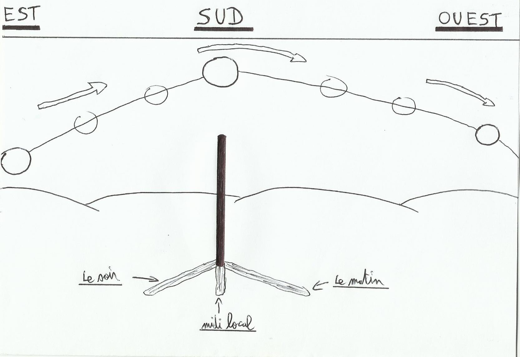
1) The sun, a stick, something to measure…And the right time
We often think that round earth discovery as a soccer ball is attributed to Christopher Columbus only, in fact reality is more complex. He has proved this empirically with his travels, but he has demonstrated a theory already thought for a long time. Several centuries earlier(5century before JC)Platon saw already earth as a sphere. In fact, Greeks had already noticed the curved nature of the Earth's surface(a vessel which is heading on horizon sees its hull disappears first, then the mast foot, and finally the rest). But in the 2nd century before JC a Greek managed through a very simple method to calculate the circumference of our soccer ball, with an incredible precision for his time(700 km only of difference with our current value!)it's Eratosthène.
His reasoning was as follows: as the earth is curved, sunbeams then reach the earth's surface at different angles. He added to it some trigonometry to season and that's all.
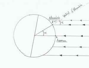
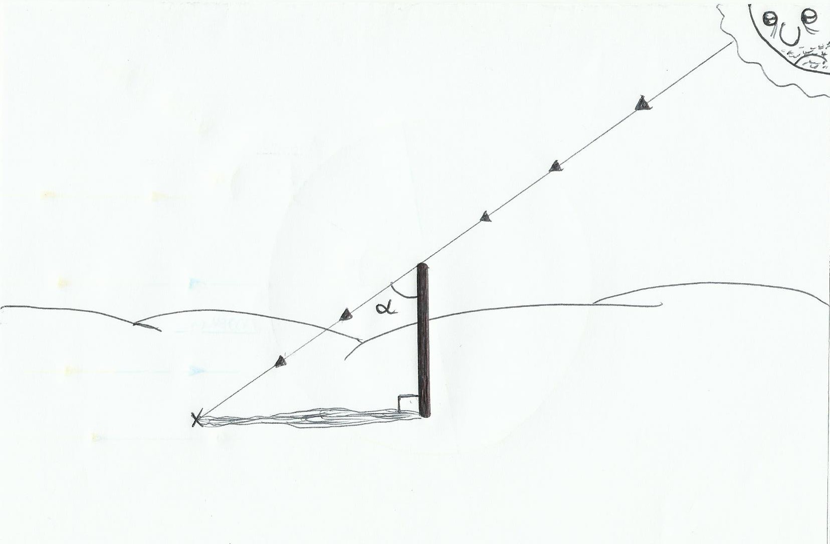
For its calculations he considered Sun's rays parallel between them(because this star relative to Earth is much larger and very far). At the time he knew that when it was 21 June(summer solstice), at local noon in Aswan vertical silhouettes drew no shadow, He therefore concluded that at that time the Sun was located on the line perpendicular to the tangent through Aswan. After all that it is easy to guess the angular distance between Aswan and Alexandria(angla alpha Scheme), by planting a stick at Alexandria and observing its shadow at local noon the 21 June, we find alpha angle.
We must plant the stick as straight as possible(Use a plumb line)to have the most accurate possible measurement(to be more accurate, use as much as possible a long and thin stick, and a good plane ground ). By knowing the size of our stick and measuring its shadow we will be able quickly to find alpha angle with some trigonometry(the ensemble has a rectangular triangle shape). Why ? because Tan(alpha)= Opposite side / adjacent side so Tan(alpha)= Shadow length / stick length. Eratosthenes has found an alpha angle of 7, 2° roughly.
As he knew the distance between the two cities, and that 7, 2° is equal to 1/50 of 360°( the total circumference of the Earth)He then multiplied the distance between the two cities by 50 which gave 39350 km( the actual value is about 40033 km).
So you will say it's very nice all that stuff but to go to Tripaille-en-Paumé we are not more informed ! Yes sure, but by taking the problem in an another way we may find our latitude, roughly anyway…
Knowing the rule of the four 21(see Article “the celestial sphere”)about the foot's position of the sun during solstices(+or- 23 ° 26′) and equinoxes(0°)in latitude. So if in this case we want to know the latitude of Alexandria we simply add the alpha angle at Aswan latitude. Aswan has a latitude of about 24 °(logical because at summer's solstice, the 21 June the foot of the sun has a latitude of 23 ° 26′, and at that date there is no shadow for vertical silhouettes in Aswan)So Alexandria latitude is 31 ° roughly.
Now in our case if we are lost the 22 September and we calculate alpha angle at local noon(to find local noon with our stick, this is when it will draw on the ground the shortest shadow in the day, because at that time the sun will be highest on the horizon), if alpha is equal to 51 ° this means that our latitude is 51 °(For the day of the autumnal equinox foot latitude of the Sun = 0 ° at local noon roughly). After that to know Sun's foot latitude all the year we must have ephemeris into our glove compartment…
Notice: if we can define with accuracy local noon hour of our position(through stick's shadow which shrinks until local noon then grows after), and if our watch is adjusted on UT time precisely, and if by miracle we have in hands ephemeris then we will be able to find our longitude too.
To find our local noon hour precisely, we will do almost the same method used for "the meridian"(see Article “The Meridian”). As the sun is at its zenith for a while, hard to find the exact local noon hour just by measuring the size of the shadow when it appears to be smaller. In fact we will take a measure of the shadow when the sun is facing south-east (by noting the time at that time) with a tensed wire from stick's foot, and we draw at the ground an arc of a circle(with a radius equal to this measurement). When the shadow will cross our draw(the sun will be closer to the west) we immediately note the time; local noon hour is then the sum of these two hours divided by two.
In the ephemeris, we find time of sun's passage at Greenwich meridian(Greenwich local noon). So if our watch is in precise time UT, that we have managed to define our local noon then we will find our longitude. The sun revolves around the Earth(in our course repository!)at a rate of 15 ° per hour(this speed is anyway indicated more precisely in the ephemeris), so our longitude =(local noon hour-Greenwich local noon hour)*15.
2) Professor Tournesol's pendulum
In the article “Coriolis”, we have seen that the more we approach the poles the more Coriolis will deflect motion things on long distances(wind and current)to the right in the northern hemisphere and left in the southern hemisphere. Conversely the more you approach the equator and the more that “force” will decrease. So parked on the church's car park between Brignolle-la-Farfouillette and Létron-la-Trine, it is reasonable to ask whether there is not a link or formula between Coriolis and the change of latitude…When we get bored to death we must deal with something!
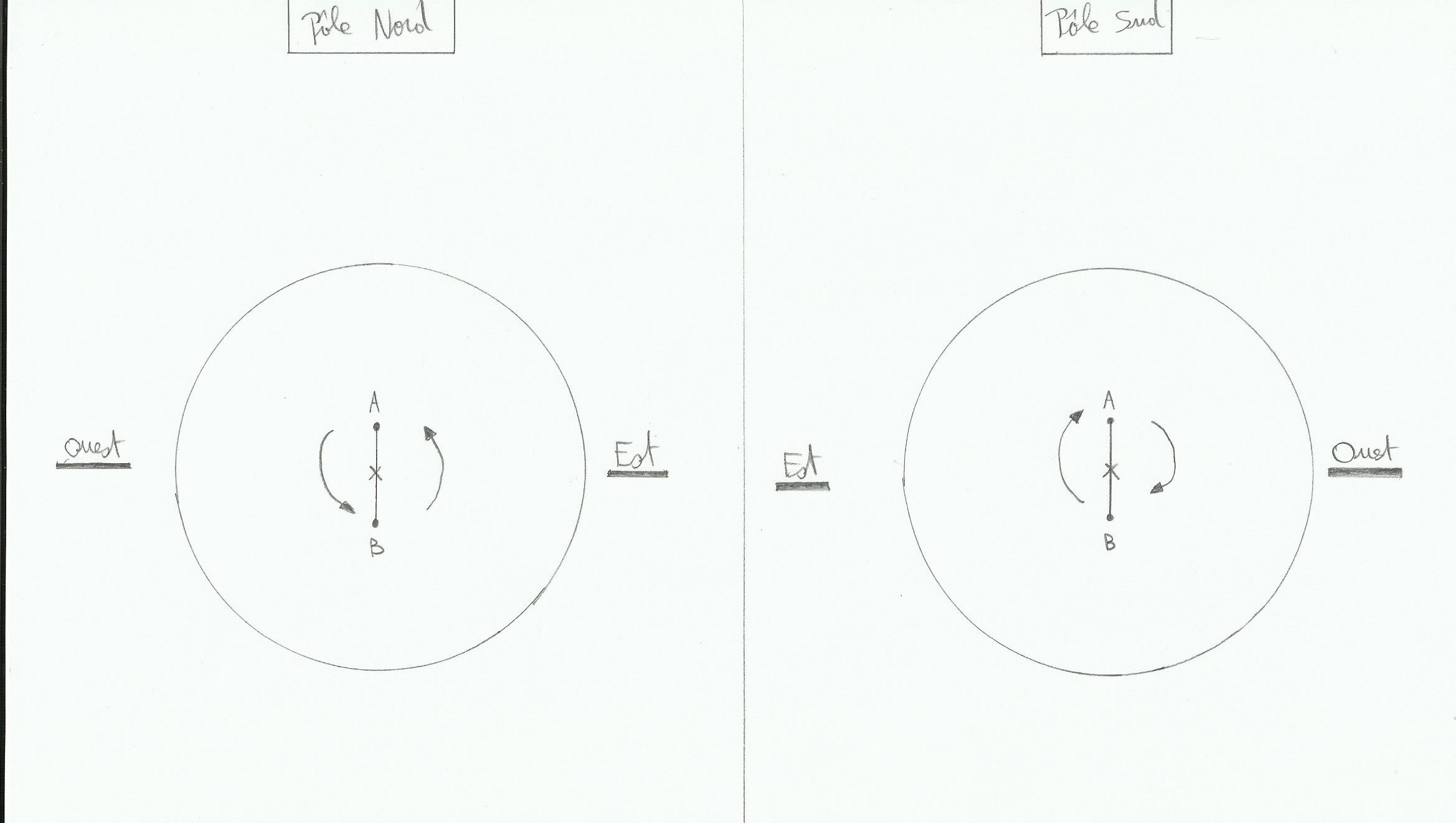
We may actually find a link through the Foucault pendulum, its principle works like a gyroscope. Basically when a pendulum oscillates(Considering the frictional forces null, the oscillating motion continues indefinitely), its oscillation's plane will remain fixed relative to earth rotation on itself, in fact it's the plan under pendulum which will turn relative to it. It is easy to deduce the rotation's speed of the pendulum's plane wether it's located on a pole:
We'll say that the pendulum swings between A and B. If the pendulum is located right on the north pole then the plane under pendulum will turn at the rate of 15°per hour roughly in anti-clockwise sense(because the earth rotates on itself 24 hours so 360°per 24 hours, and the sun falls in the West). On the south pole it will be the same rate but in clockwise sense,
and at the equator as Coriolis is null the plane will be motionless relative to the oscillating plane of the pendulum
a. But then at Brignolle la Farfouillette, how it goes? In fact it creates an apparent motion of the pendulum in the opposite sense(North Pole, the pendulum rotates clockwise and at south pole counterclockwise).
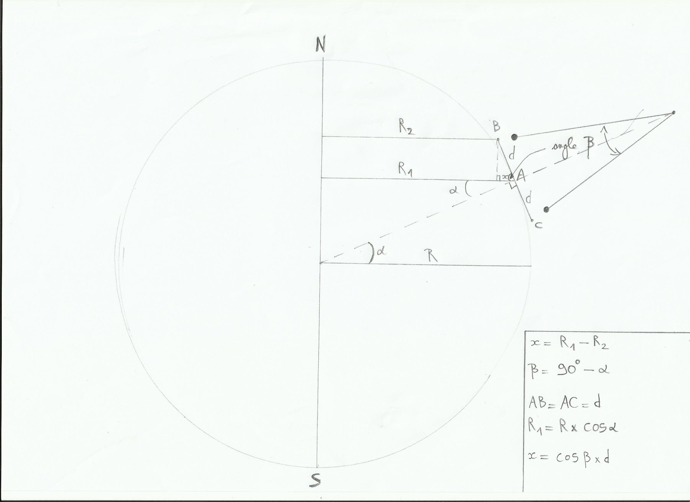
And then the speed will depend on the latitude of the pendulum, due to the difference of linear velocity according to latitude. On the following diagram points B, A and C are located at different latitudes, their angular earth velocity is the same (360° in 24 hours), but not their linear velocity(because earth circumference decreases when the latitude increases, so the point will have less way to follow in 24 hours, so its linear speed will be slower if its latitude increases. In this diagram the center of the pendulum is A and it's oscillating between B and C; A's latitude is alpha angle and R is earth's radius:
The linear speed of A is equal to the angular velocity of the earth(w) multiplied by R1 so Va = w *R1; R1=cos(alpha)*R. Then Va=w*cos(alpha)*R.
Vb=w*R2, and R2=R1-x. x=cos(beta)*d with trigonometry, or angle bêta=90°-alpha so cos(90°-alpha)= sin(alpha). x=sin(alpha)*d. Donc R2=cos(alpha)*R-sin(alpha)*d, Vb=w*(cos(alpha)*R-sin(alpha)*d)
With a similar reasoning we find Vc=w*(cos(alpha)*R sin(alpha)*d)
Finally we see that Vc>Va>Vb, and between each of these speeds the difference is w * sin(alpha)*d. This difference between the speeds will create the apparent motion of the plane under the pendulum. We can deduce that the angular velocity of this plan is w * sin(alpha), or the angular velocity of earth multiplied by latitude's sinus(we remove d which is plane's width, Independent of the angular velocity). To conclude we can write this equation:
rotation angle per hour = 15 * sin(latitude)
(Notice: On the poles with latitudes of 90 ° we find this principle above, just as with a latitude of 0 ° at the equator.)
3) Recall
Polaris height relatives to horizon give our latitude too(article “our position without GPS or calculator”). After that I have not tried it yet but knowing that Mintaka(Orion) is located almost on the celestial equator, maybe its height above the horizon without 90 ° gives our latitude…maybe. Alternatively to find our way we may ask our position to the first pedestrian met, it will be faster!
A rainy Halloween's afternoon, while television shows only a derrick episode in original version and you have just received your bills, Be careful boredom and depression could come quickly…but well what can I do? empty the fridge? count bathroom's floor slabs? learn by heart the phone book just for fun? organize a Mikado tournament with my dog? So so… Ho no but I can make a compass instead! So I will finally know if my toilet door is exposed north, south… Since that time I asked to myself this important question, now it's time to find an answer!
1) Gear used
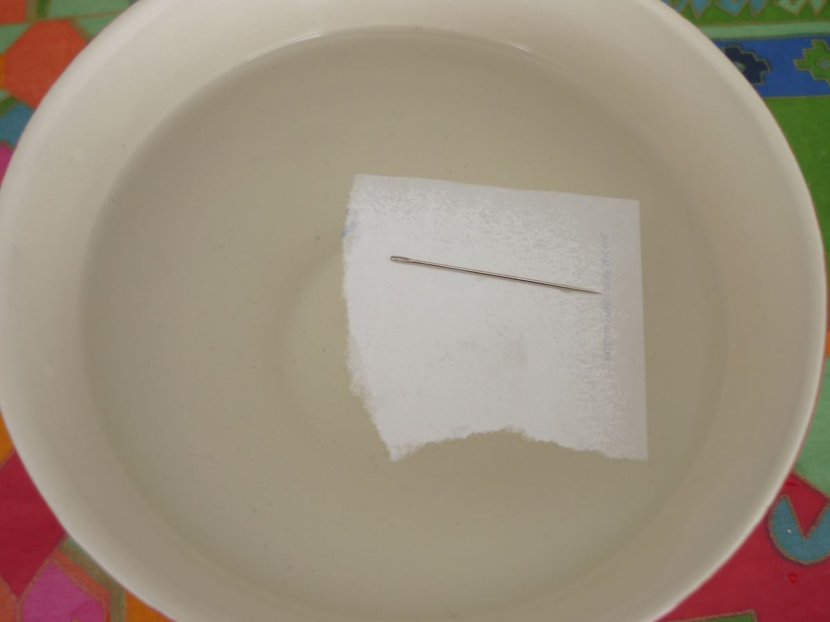
We need a sewing needle, a bowl or soup plate, a magnet, a small piece of thin cardboard, a battery of 4,5 volts like square batteries used for old torches, and if you have it in your surroundings a little enamelled copper wire(it can be found into an old radio set for example, it is a copper wire with an isolating varnish on).
2) How it goes
First the bowl is filled with water(with a less dense liquid like oil it works better but water is enough), then we take the needle and the magnet. We will then rub the needle with the magnet but always in the same direction(no go and back, we rub from the head to the bottom, from the head to the bottom…)for 5 minutes and then we put the needle on the cardboard, and cardboard on the water in the middle of the bowl. After a moment the needle will stop turning on itself and stabilize in the north/south axis(very efficient to chat up in nightclub).
By rubbing this needle from head to pic, the pic side of the needle indicates the south.
We can also magnetize the needle if it's wrapped with a varnish copper wire, then we connect 2 wire's ends with terminals battery(do not forget to sand the varnish at the wire's ends to make it work, if the battery heats after a short time then it works)but with a magnet it's more easy for the same result.
3) With a neodymium magnet
The most efficient thing is the use of a neodymium magnet instead of the needle. Very quickly he will move until the north/south axis.
The neodymium magnet is so powerful that you can even forget water's bowl, by maintaining it balanced on the thumbnail it will turn and come into the north / south axis alone(David Copperfield could be impressed!).
(Notice: If you apply this method and you can simultaneously see Polaris Star, you will be able to find the declination of your place without gps or compass, okay it's not very useful but at least it has kept you busy for the evening…)
To learn about celestial navigation, we think it is essential to buy a sextant. The first prize for this instrument is the mark 3 which costs around sixty euros. For more accurate measurements of its position, price increases quickly…and inversely proportional to the motivation to learn which can quickly decline. Indeed, why bother to spend money and then do calculations if with the same price you can have a good quality gps? The following small method not spend money more than ten euros, but it also provides a measure of star heights without the need to distinguish the horizon.
1)Equipment
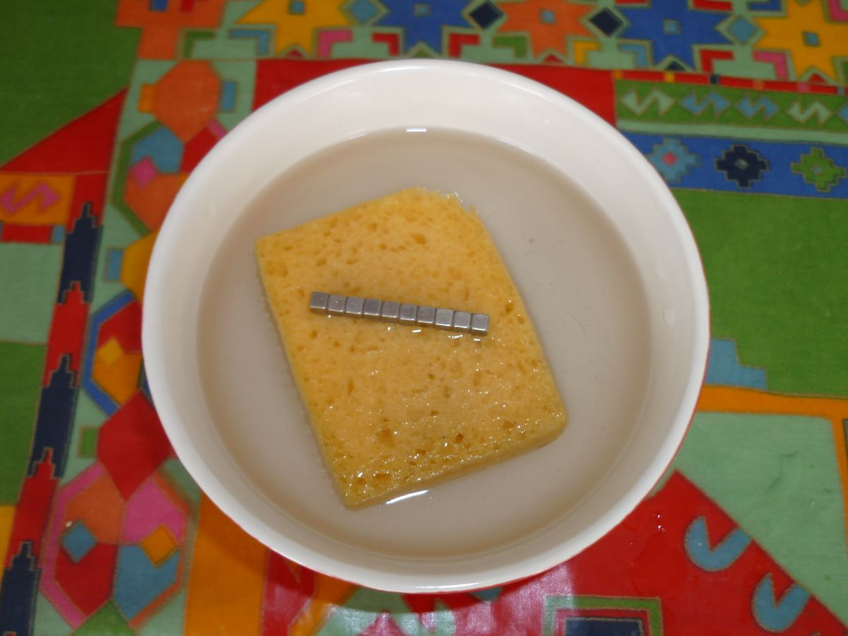
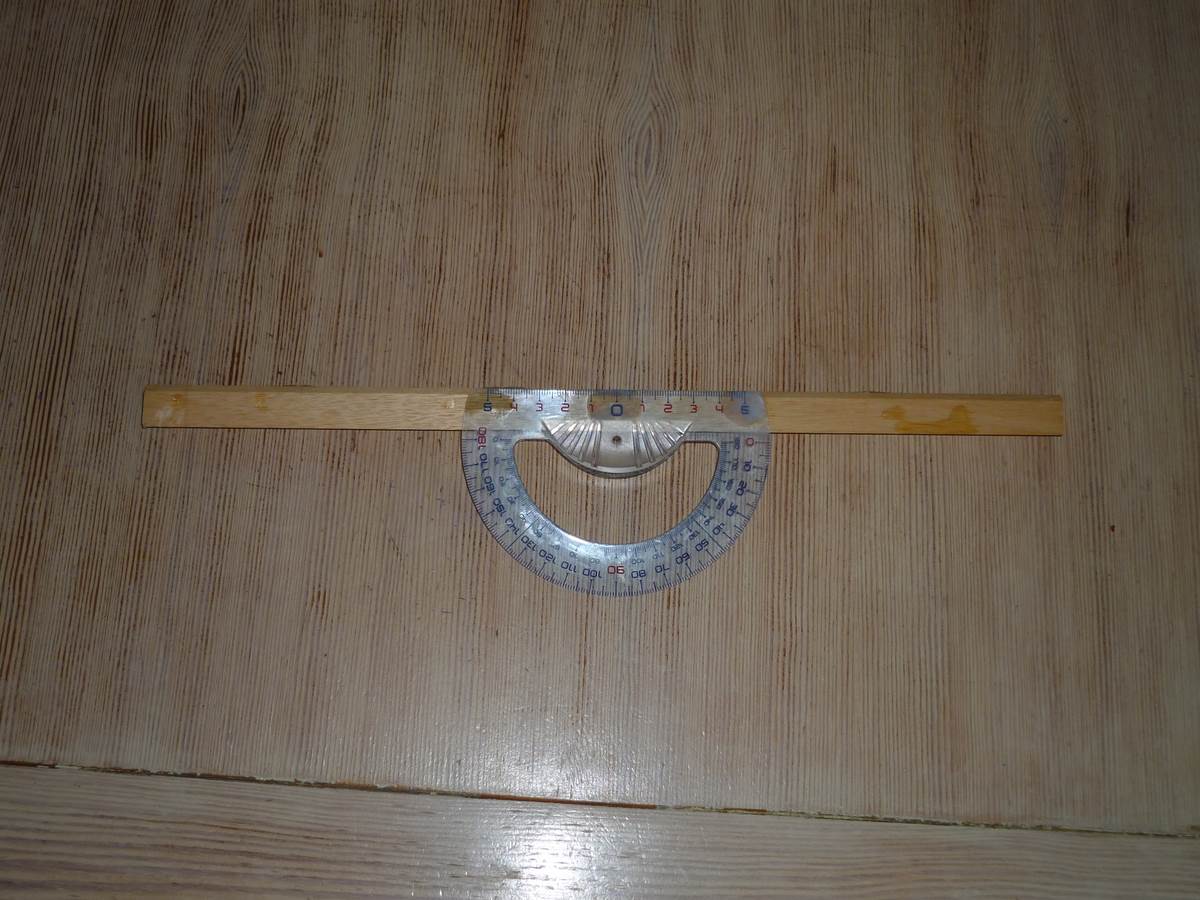
Just have on hand a cheap plastic protractor, a long string (one meter, one meter and a half it's enough)and thin, something with weight(one or more large nuts for example)and a piece of wood or long plastic , straight and square. A small tube of glue will allow us to stick the protractor on the piece of wood or plastic as follows:
we have to be careful, we must stick the straight edge of the protractor in line with the straight piece of wood or plastic.
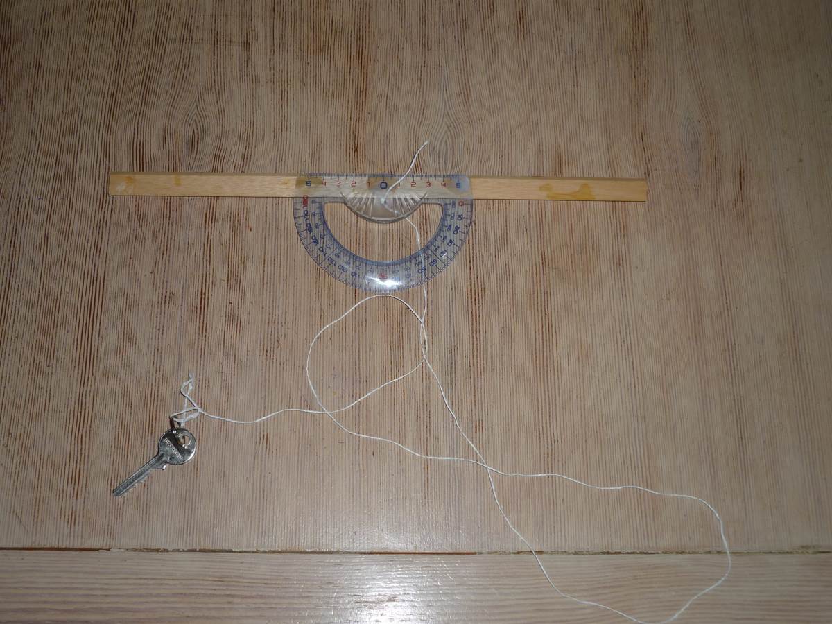
Then the wire is passed through the small ground hole of the protractor, we make a figure of eight knot and at the other end we link the weight stuff(nut, keys, stoolbox...)(for the photo I put a key, As there is a little weight the rest does not matter).
That's done! It is used as follows:
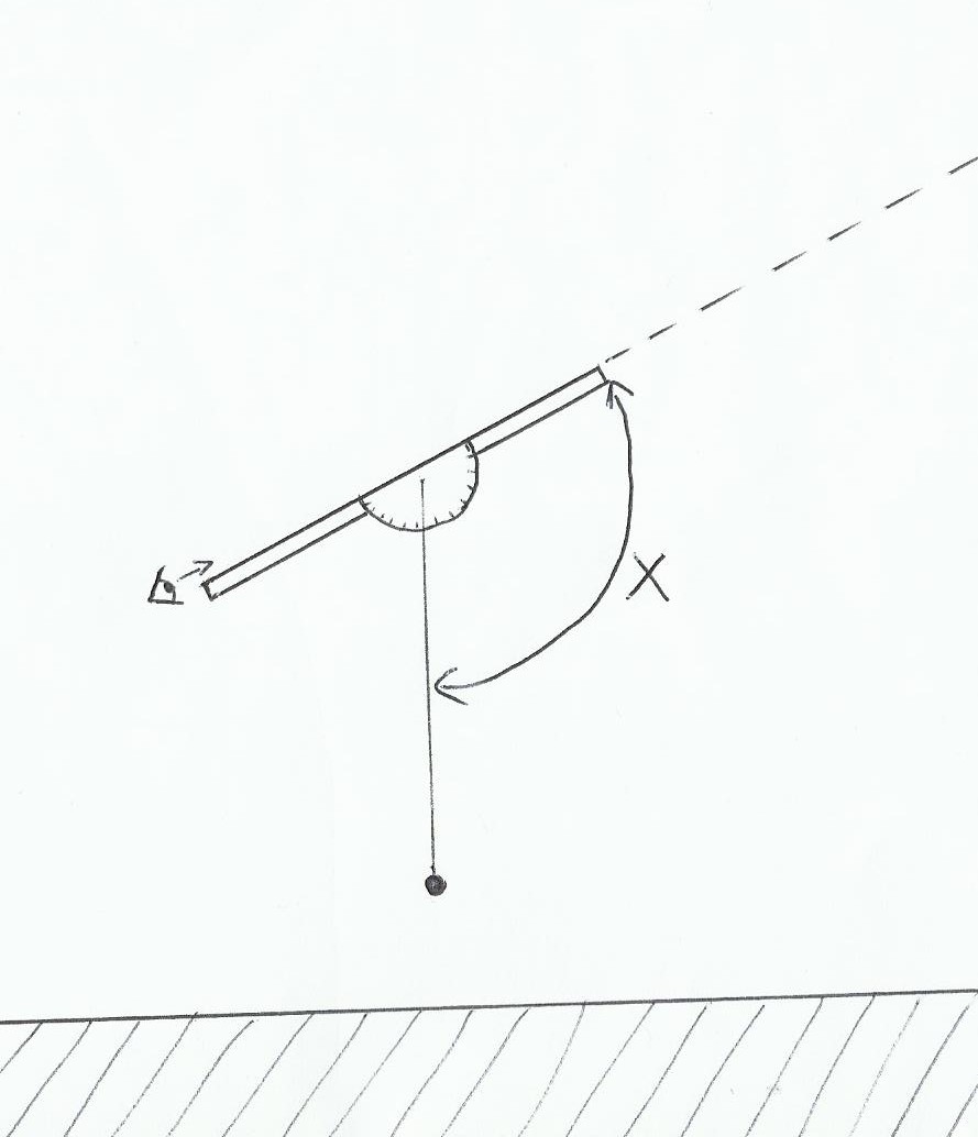
The more the wooden stuff is long, straight, and the wire is thin and pulled, the more we gain in efficience. You can also install the unit on a tripod with a swiveling axis to make more accurate reading without tremor during measurement.
The height's measurment of the star is fund by removing 90 °:
2)Advantages / disadvantages
This method has the distinct advantage of measuring the height of a star without the need to distinguish the horizon, so it can be done in town for example, view of the star is enough. However onboard the sea must be like a mirror and the boat without way, if the weight stuff moves then we will not be able to measure the height. To make a more elaborate sextant you can read the page of the site on how to make an electronic sextant with arduino.
This is a very simple rule discovered mainly by Snell, a dutch scientist. It focuses on the refraction of light in different materials. This rule is very important because it explains the mirages, why a submerged object deforms, why fishermen are sitting near the edge when fishing instead of standing and some corrections to be made between the true height and instrumental height(see “the meridian”). It also explains how to have a successful mayonnaise and winning the lottery(no, Just kidding not my best joke I guess…).
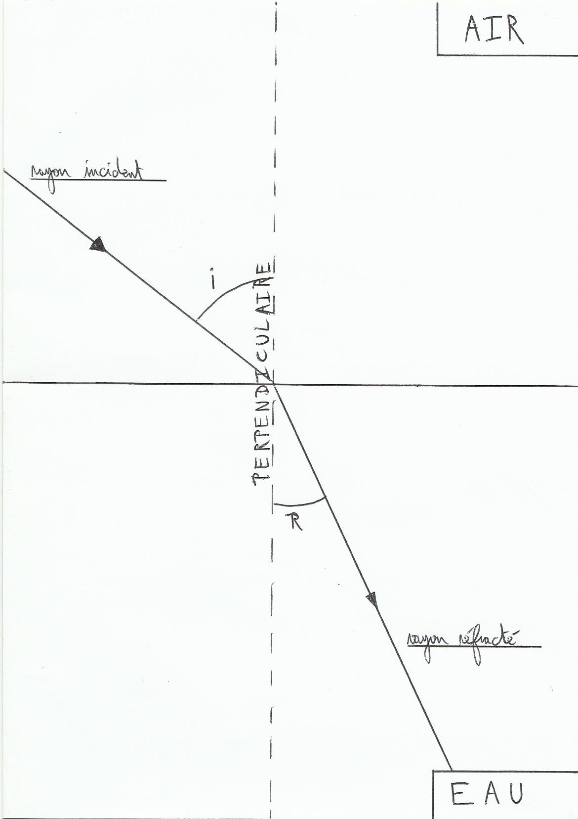
1)Main idea
The light propagates in vacuum space at the rate of about 300000 km/second, but when it crosses a denser material(for example from vacuum to air, air to water or a hot air to cold air which is denser)it slows, This also has the consequence to deflect lightrays. Main things, a ray which crosses a denser material where it slows approaches the perpendicular line to the boundary between the two materials. Light differs in reverse sens. The more difference in density between materials is strong the more ray is deflected.
We can put it all in that form, N1*sin(i)=N2*sin(r).
N1 is the air refractive index and N2 is for water. This is a number useful to evaluate the capacity of the material to deflect light, the higher the index is, the higher the light is deflected(the strongest index is found with diamond: 2,42, there is no unity). This index is the ratio between the speed of light in the environment concerned and in a vacuum space, vacuum thus has an index equal to one, a material with an index of two slows the speed of light by two(diamond thus slows the light almost 2,5 times higher than in the vacuum).
(Notice: Tools such as refractometers use this rule to measure concentration in a product, for example.)
2)Applications
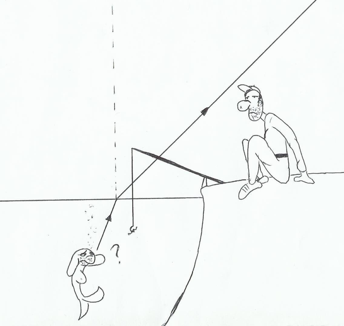
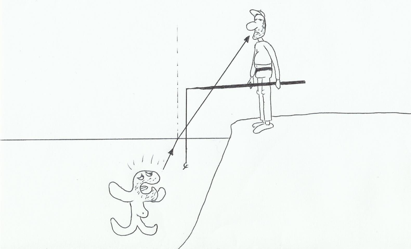
One of the most significant examples is the fisherman and the fish. Due to the deflection of light, they don't see the same things, in fact not on the same angle…
Here, flipère the trout do not see Mr Igloo…
Damned! Flipère has guessed the trap!(excuse me it's late…).
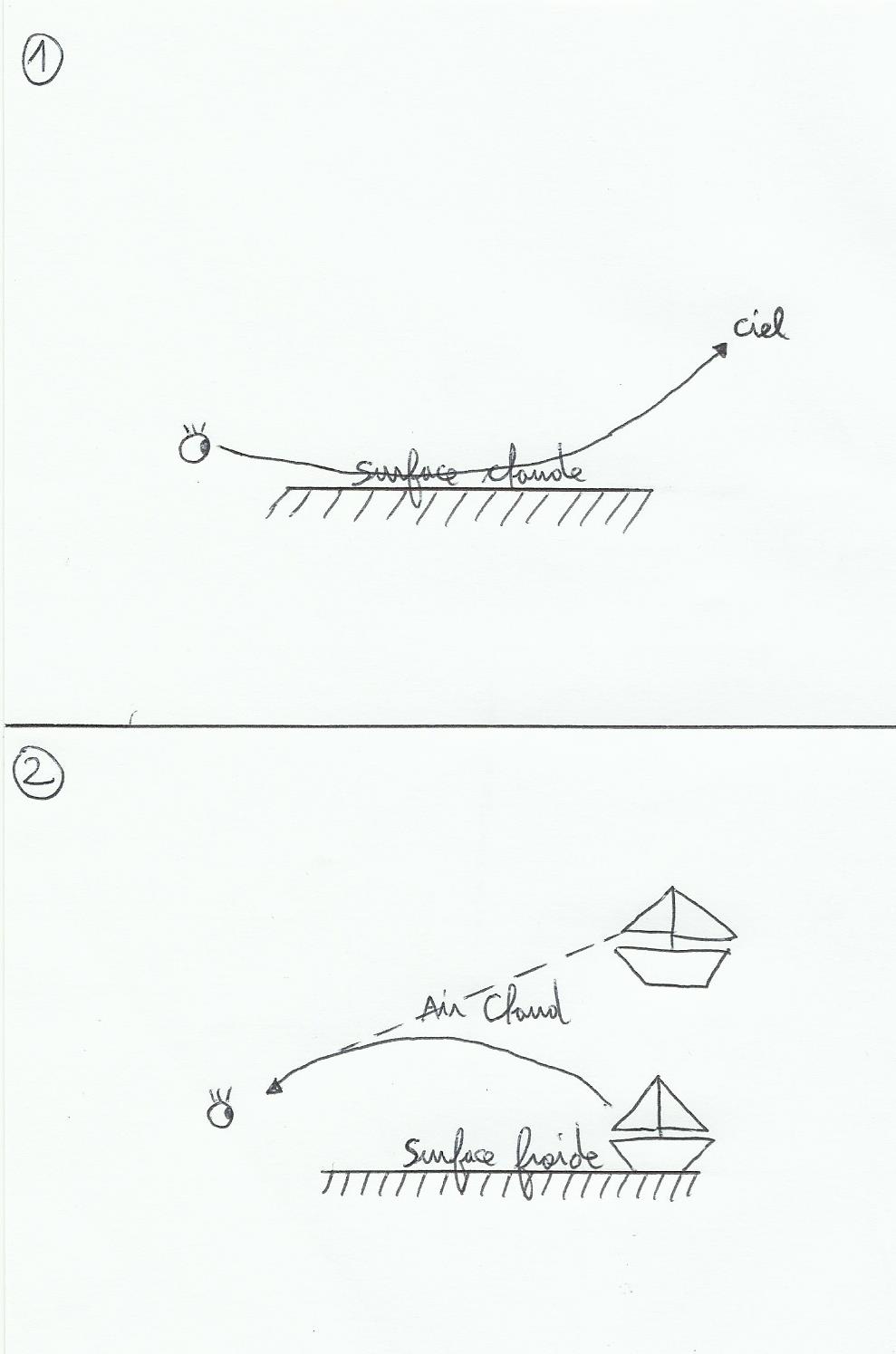
The refractive index of air change with temperature, so rays are deflected and the object seen appears to come from elsewhere, this is the mirage:
Case 1 is easily noticeable in summer on paved roads thus more gifted to keep heat, it's like to see the waves on the horizon; in fact it is the sky that we see. If the temperature changes quickly depending on the height above sea, the rays from the bottom of the object will be more deflected than the top, the object may seem reversed.
Another notable effect, light perceived by the sun. The sun appears higher in the sky than it really is and flatter in its height. The first cause is the refractive index which varies in different layers of the atmosphere(further down in altitude, more the index increases as the air density increases)and the second reason is the lower edge of the sun appears more pointed than the top(always with the history of index changing).
This phenomenon is taken into account in celestial navigation, to determine the true height of the sun from the instrumental height, and also when we use star to find our position; it's better to choose the highest stars in the sky(so light sent less undergoes deviation). This correction is grouped with three other angles corrections, we find the tables in the ephemeris(the other three corrections are depression of the horizon, parallax and semi-diameter of the sun).
For comic lovers, Newton is a character of "rubrique à brac"(Gotlib) who has the gift to receive an apple dropped on his head in all circumstances, and incidentally it was a great scientist known for his work on optics, mathematics and in our case the laws of gravitation. These laws explain the tides.
1First law: motion quantity(Q) is equal to the product of the mass(M) of the body in motion and its speed(V). Q=M*V, the more an object is heavy and fast the more it's a pain to stop it.
2rth law: The forces amount applied to an object in accelerated motion is equal to the mass of the object multiplied by its acceleration. If the object is at rest state(with constant speed or stationary)then according to the first formula it's equal to 0.
3rth law: A force applied to an object creates a counterforce(ex gravity force / buoyancy force(Archimède))with the same direction and intensity but with opposite direction.
4rth law: The gravitational force(Fg) present between two bodies is equal to the gravitational constant(Gn)multiplied by the two masses of the stars(M1 and M2) and divided by the distance between them multiply by itself(D multiply by D). It is a law of inverse square, the gravitational force intensity decreases very quickly when the separation distance of the stars increases slightly.
Fg=Gn*M1*M2/(D*D)
1)Basically how it works?
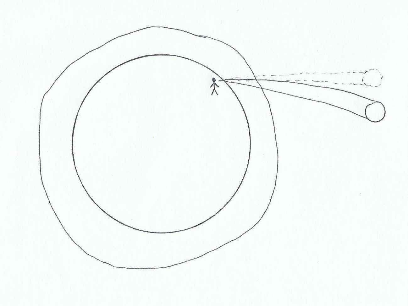
The earth has a major surface made of water, this surface deforms itself(few centimeters)offshore in the intertropical area under gravity action(Sun and Moon influence).
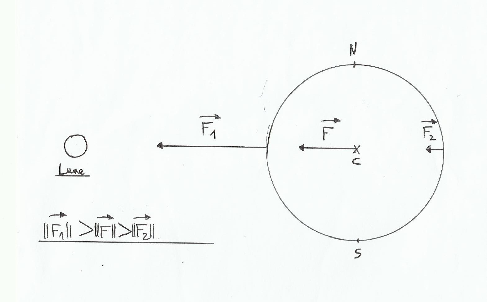
The gravity force is not reflected in the same way on the globe, it is stronger near the Moon. We can deduce that there are two high tides at points origins of F1 and F2(because on F2 the force of gravity is lower, centrifugal force is the stongest). With the help of the fourth law we can calculate F, F1 and F2.
F=Gn*Mlune/D(Earth and Moon)multiply by itself
F1=Gn*Mlune/D(Earth and Moon-Earth radius)multiply by itself
F2=Gn*Mlune/D(Earth and Moon Earth radius )multiply by itself
Mlune= 7.36 * 10 power 22 kg
D(Earth and Moon) = 384000000 m
earth radius = 6350000 m
Gn = 6,67*10 power -11 m 3/kg/seconds
With a calculator we obtain :
F approximately equal to 3,3*10 power -5 meters per second, F1 3,4*10 power -5 meters per second and F2 3,2*10 power *-5 meters per second. The tidal force noticed at the ocean surface is the difference between F and F1 and F and F2. So this force is equivalent to approximately 1*10power -6 meters per second with the Moon only. It's fun to do the same with sun data(weight and distance Earth / Sun)we find roughly 0,5*10 power -6 meters per second(we can see the inverse square law of the distance, although the sun is huge, its high distance from Earth reduces considerably its influences. However, if Mercury planet would have water, it would make a noticeable tide !).
The moon undergoes from earth a tidal force too, much more powerful (F3), that 's why it always shows its same face; Over the centuries this force has made the rotation period of the moon equal to its period of revolution around the earth, in short it is a bit of a mess…
moon radius = 1750000 meters
earth weight = 5,97*10 power 24 kg
F3 = Gn*Mterre/D(Earth and moon-moon radius) multiply by itself
F4(lune center) = Gn*Mterre/D(Earth and Moon) multiply by itself
the tidal force on the moon is = 3*10 power -5 meters per second, 30 times stronger than force played by the moon on earth!
2)Why on the coast a few tens of centimeters becomes in meters(this title is rotten!)